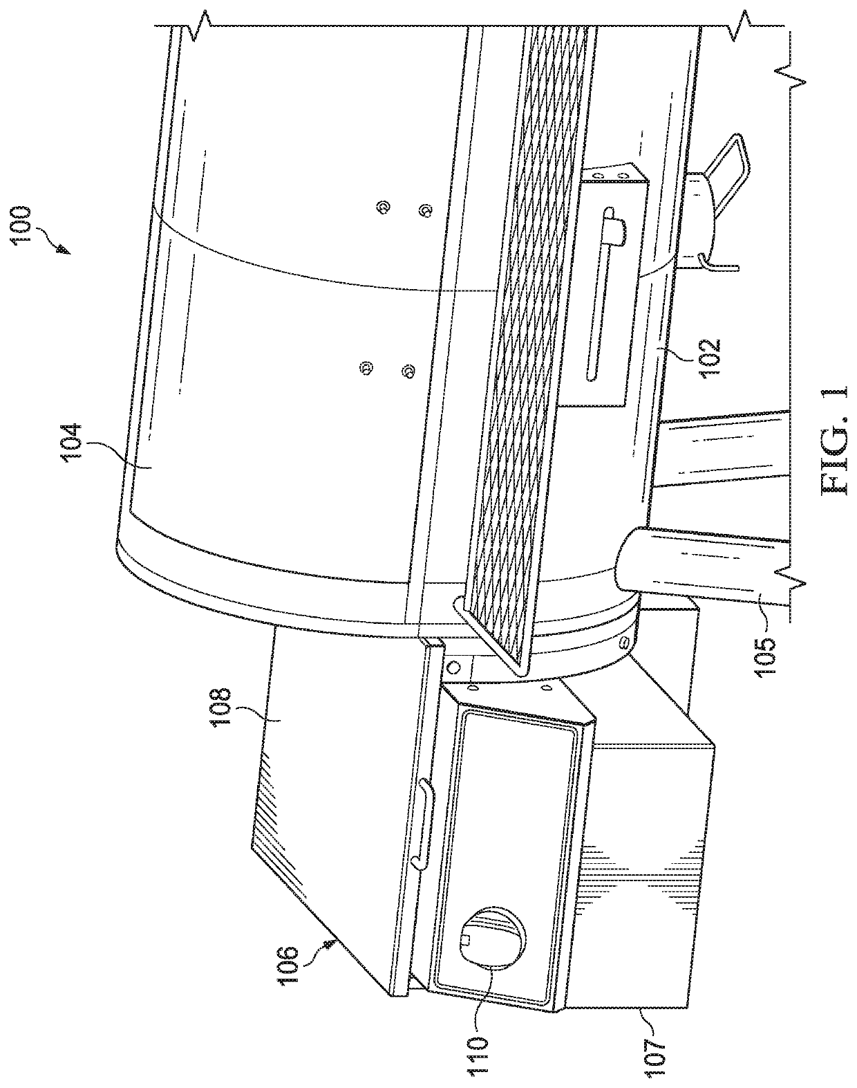
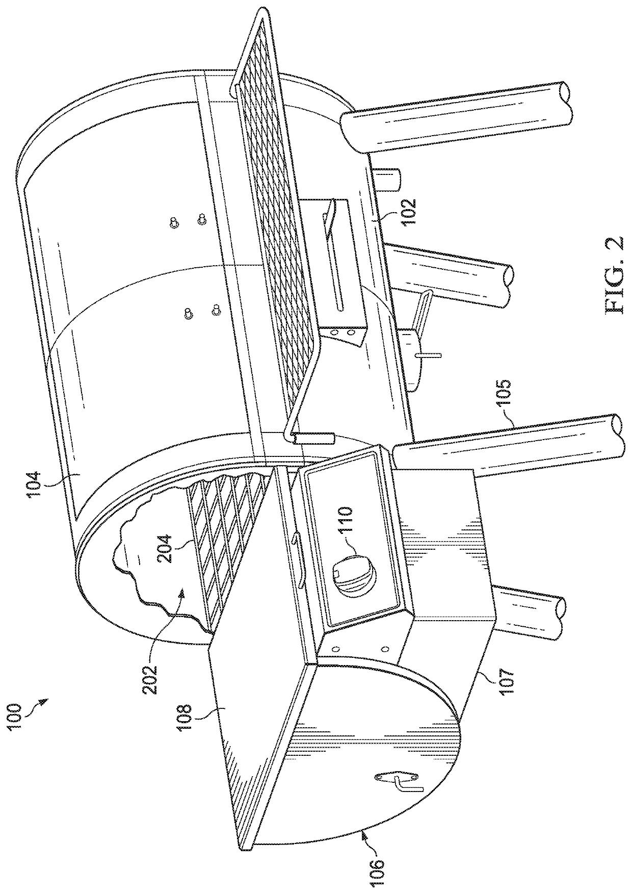
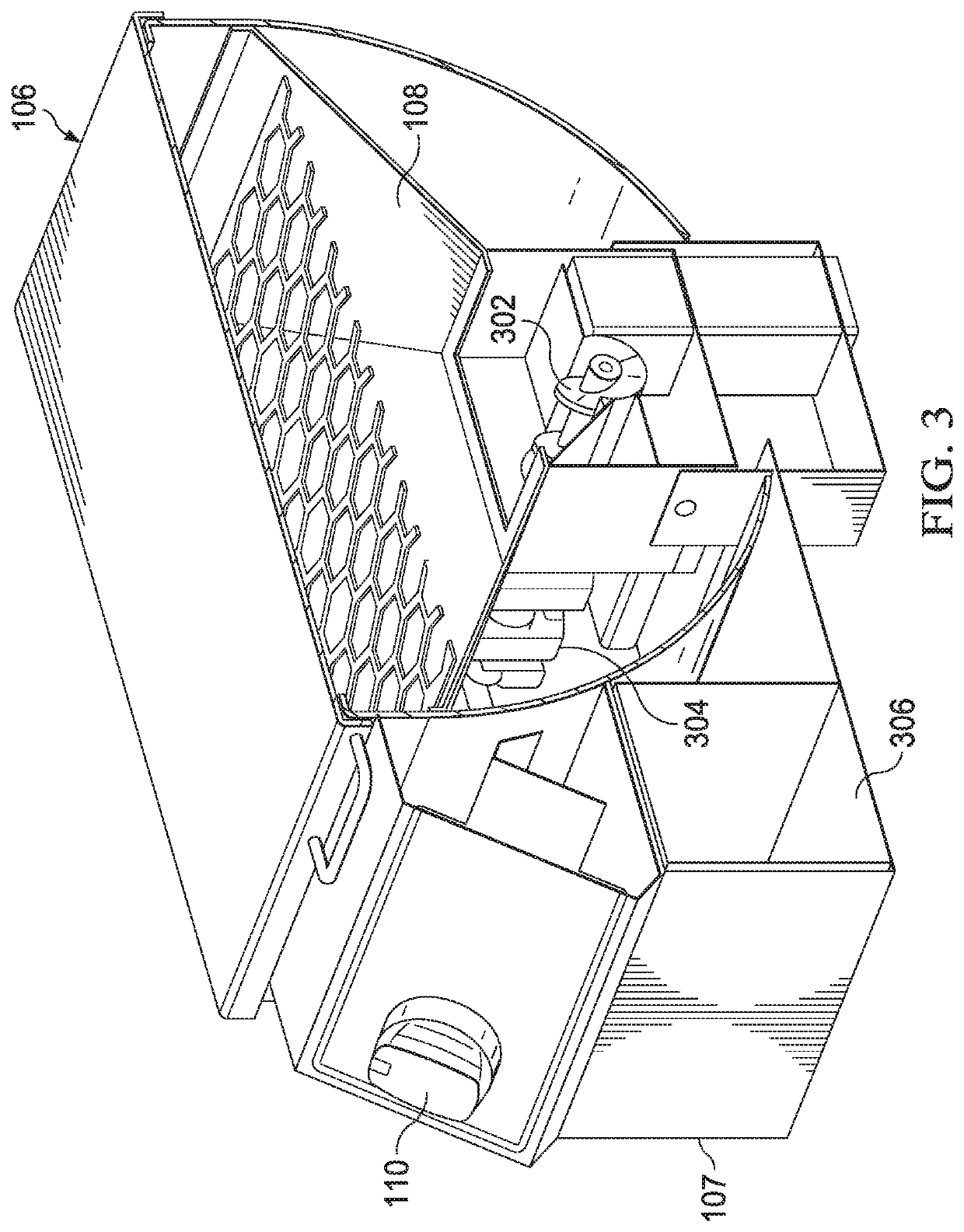
Battery enabled pellet grill

a technology of battery-enabled pellet grills and cooking grills, which is applied in the field of cooking grills, can solve the problems of inoperable pellet grills or smokers so configured

Inactive Publication Date: 2020-07-09
W C BRADLEY CO
View PDF1 Cites 16 Cited by
  • Summary
  • Abstract
  • Description
  • Claims
  • Application Information

AI Technical Summary

Problems solved by technology

The pellet grill or smoker so configured is not operable without a steady supply of household A / C power.

Method used


Image

  • Battery enabled pellet grill
  • Battery enabled pellet grill
  • Battery enabled pellet grill

Examples


Embodiment Construction

[0022]In association with a pellet grill or smoker, demand for electrical power may be considered as being comprised of a continual or intermittent demand for combustion air (depending upon when or how the product is being operated), and an intermittent demand for an auger feed and ignition (often linked together in frequency of occurrence). Variable on / off cycles may be employed to obtain different heating rates. In various embodiments, a peak power demand during operation is on the order of 250 to 300 watts.

[0023]Since pellet grills and smokers are often used for long cooking cycles of 2 to 8 hours, the total amount of energy needed to complete a cook cycle may be on the order of 500 watt-hours. This is entirely beyond the capacity of commercially available primary cells (non-rechargeable batteries). Customarily 110-120 V A / C power from household circuits is therefore utilized. This brings with it a number of disadvantages, including difficulty in locating the grill or appliance t...


PUM


Abstract

A system includes a cooking chamber defining a space for food to be cooked, a firepot inside the cooking chamber that is configured to utilize pelletized fuel to provide heat or smoke within the cooking chamber for cooking the food, and a fuel hopper defining a storage space for the pelletized fuel before delivery to the firepot. A battery powered auger interposes the fuel hopper and the firepot and is configured to selectively convey the pelletized fuel from the fuel hopper to the firepot for combustion. A rechargeable battery selectively provides power to the auger.

Description

CROSS REFERENCE TO RELATED APPLICATION[0001]This application claims the benefit of U.S. provisional patent application Ser. No. 62 / 788,508, filed on Jan. 4, 2019, and incorporates such provisional application by reference into this disclosure as if fully set out at this point.FIELD OF THE INVENTION[0002]This disclosure relates to cooking grills in general and, more specifically, to battery-enabled pelleted-fueled cooking grills.BACKGROUND OF THE INVENTION[0003]Pellet grills and smokers have been available since the mid-1980's. Some of these were based initially on U.S. Pat. No. 4,823,684 to Traeger et al. and U.S. Pat. No. 5,251,607 to Traeger et al. In their current state pellet grills or smokers may include a hopper, into which is loaded wooden fuel pellets. An electrically driven auger may be provided for conveying the fuel to a combustion chamber or firepot, in which the fuel is ignited, typically by an electric hot surface ignitor. Air may be supplied to the firepot by an elect...

Claims


Application Information

Patent Timeline
Patent Type & Authority Applications(United States)
IPC IPC(8): A47J37/07A23B4/052F23B40/00
CPCA47J37/0754F23B40/00A47J37/0704A23B4/0523A47J37/079A23V2002/00F23B40/04F23B2900/00001F23K3/14F23K2203/202F23B20/00A23B4/052A47J37/0786
Inventor GAFFORD, ALEXRAHMANI, RAMIN KHOSRAVI
Owner W C BRADLEY CO
Why Eureka
Try Eureka