Automated method for verifying manufacturing process control interlocks

a manufacturing process and interlock technology, applied in the field of automatic verification of manufacturing process control interlocks, can solve the problem of costly testing of control system interlocks

Inactive Publication Date: 2020-07-09
BOUDREAU DAVID THOMAS
View PDF0 Cites 3 Cited by
  • Summary
  • Abstract
  • Description
  • Claims
  • Application Information

AI Technical Summary

Benefits of technology

[0004]The invention is a method used to enable a modern control system to continuously monitor itself to document and verify that the control system interlocks are functioning as designed and can shut down the process when needed. The invented method enables the control system to detect any malfunctioning interlock. The new interlock verification method was bought to fruition with the creation of a control system program referred to as a Control System Interlock Monitor. This method can be utilized by any type of control system that provides the user with the ability to create control system entities and customs interlock monitoring programs for any type of process. The control system can utilize information provided by control system processors and logic solvers that react to various conditions of the devices used for the interlocks. The interlocks can be comprised of programming, software logic and settings, hardware, hardwired and communicated interconnections between the various control system processors a

Problems solved by technology

Such traditional interlock testing only proves the interlock and control system can properly shutdown the process and related process equipment at that

Method used


Image

  • Automated method for verifying manufacturing process control interlocks
  • Automated method for verifying manufacturing process control interlocks
  • Automated method for verifying manufacturing process control interlocks

Examples


Embodiment Construction

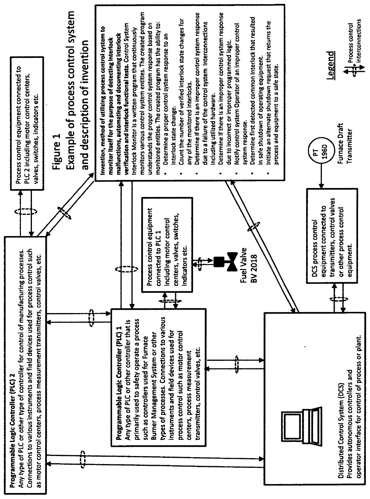
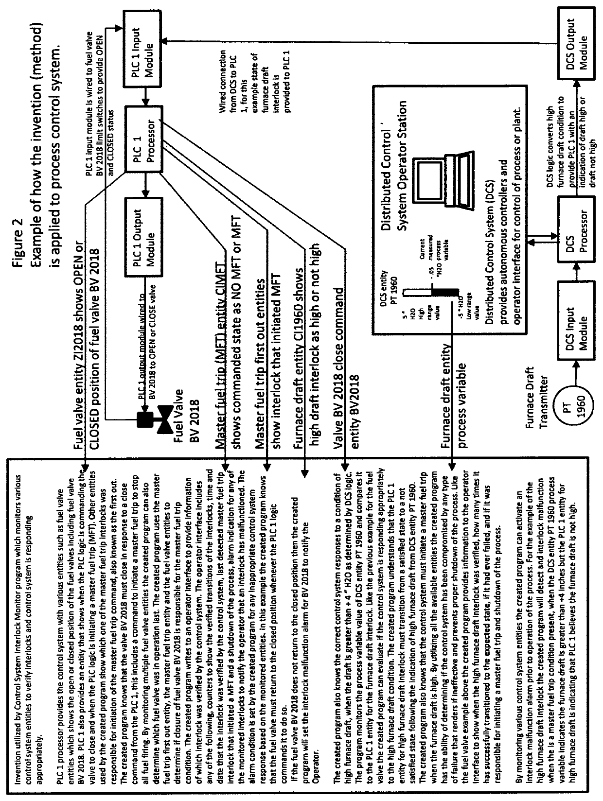
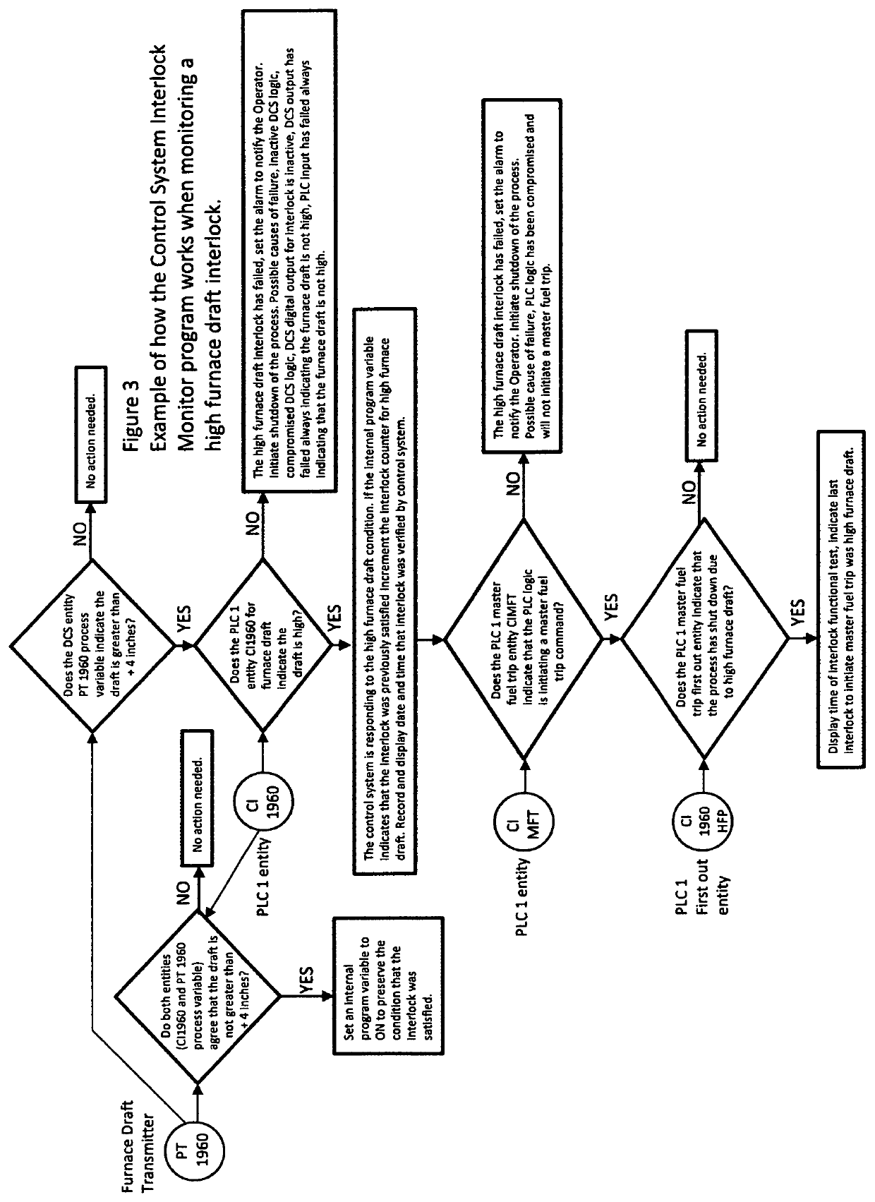
[0010]The invented method of automating interlock verification can be applied to any control system that has the capability of monitoring the control system interlocks. This disclosure exemplifies the principles of the invention and is not considered to limit to the broader aspects of the invention to the particular embodiment as described.

[0011]The new method requires the user create a Control System Interlock Monitoring program. The created program gives the control system the ability to continuously monitor its response to various operating conditions and state changes of the interlocks. The created program can be structure text or other types of programming that are available to the programmer and inherent to the process control system in use. The created program must perform all the functions that would be included in traditional interlock testing, such as documenting and verifying the proper control system response. The programmer needs to understand the methods of programing ...


PUM


Abstract

The present invention discloses a method for automating process control interlock testing, verification and documentation. Various control system entities can be utilized by a created control system program that understands the required response of the control system to various operating conditions and interlocks. By continuously monitoring control system entities the created program evaluates the control systems ability to shut down the process and equipment. The automated method verifies that all utilized control system programming, software, hardware, communicated and/or hardwired interconnections are working properly. The automated method and continuous monitoring can determine that an interlock is incapable of shutting down the process as required and can notify the operator of a failed or malfunction interlock. A created control system program can provide historical data to an operator interface to for the purpose of documenting which interlocks were verified by the control system and which had initiated a shutdown of the process. The technical solution of the present invention provides the earliest detection of a failed or compromised interlock.

Description

BACKGROUND[0001]Process control system interlocks need to be tested on a frequent basis to ensure the interlock can shut down the equipment and process to avoid operating the process equipment in an unsafe manner.[0002]Traditional interlock functional testing such as recommended by Black Liquor Recovery Boiler Advisory Committee Instrumentation Checklist and Classification Guide requires creating or simulation process control conditions that initiate a response from the control system to verify that the interlock and control system has the ability to shut down the process. It is acceptable to test one interlock all the way through to the initiation of equipment shutdown and movement of the final controlled equipment to a safe state or desired position. Other interlocks that would also initiate the same process shutdown can be tested to common logic of the control system. Such traditional interlock testing only proves the interlock and control system can properly shutdown the process...

Claims


Application Information

Patent Timeline
IPC IPC(8): G05B19/042
CPCG05B2219/21159G05B19/0428
Inventor BOUDREAU, DAVID THOMAS
Owner BOUDREAU DAVID THOMAS
Why Eureka
Try Eureka