Hydrogen filling system and hydrogen filling method

a hydrogen filling system and hydrogen filling technology, applied in the direction of electrochemical generators, liquid transfer devices, container discharging methods, etc., can solve the problems of high hydrogen filling rate and inconvenient hydrogen filling, and no technology for dealing with the above inconvenience has been proposed

Active Publication Date: 2020-07-16
TOKYO TATSUNO CO LTD
View PDF0 Cites 3 Cited by
  • Summary
  • Abstract
  • Description
  • Claims
  • Application Information

AI Technical Summary

Benefits of technology

[0015]With the present invention having the above construction, in communication filling, when there is an abnormality in measurement value of pressure or temperature in an in-vehicle tank (IT), communication filling is converted to non-communication filling. When there is an abnormality in measurement value of pressure or temperature in an in-vehicle tank (IT), it can be judged to be a state where pressure or temperature in an in-vehicle tank cannot be transmitted accurately on a hydrogen filling device side. Then, in case of non-communication filling, filling rate is set to be lower than that of communication filling, so that converting to the non-communication filling allows hydrogen filling to be performed at low filling rate, that is, on the safe side, which prevents hydrogen being filled up to the limit of the in-vehicle tank (IT), that is, full tank. In other words, when there is a fear that pressure or temperature in an in-vehicle tank (IT) is not accurately transmitted on the hydrogen filling device (1) side in communication filling, it is converted to non-communication filling, which is more space to spare on the in-vehicle tank (IT) side, that is, to a safety side, in such a case, hydrogen filling can be carried out in safety.

Problems solved by technology

In such cases, continuing communication filling may cause an inconvenience that hydrogen is filled at high filling rate in the same manner as the communication filling despite a condition that pressure, temperature and so on in the in-vehicle tank are not precisely grasped.
But, no technique for dealing with the above inconvenience has not yet been proposed.

Method used


Image

  • Hydrogen filling system and hydrogen filling method
  • Hydrogen filling system and hydrogen filling method
  • Hydrogen filling system and hydrogen filling method

Examples


first embodiment

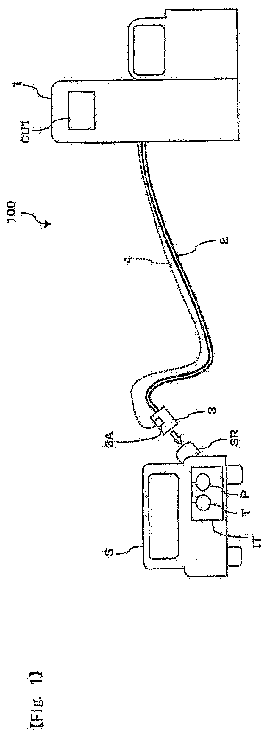
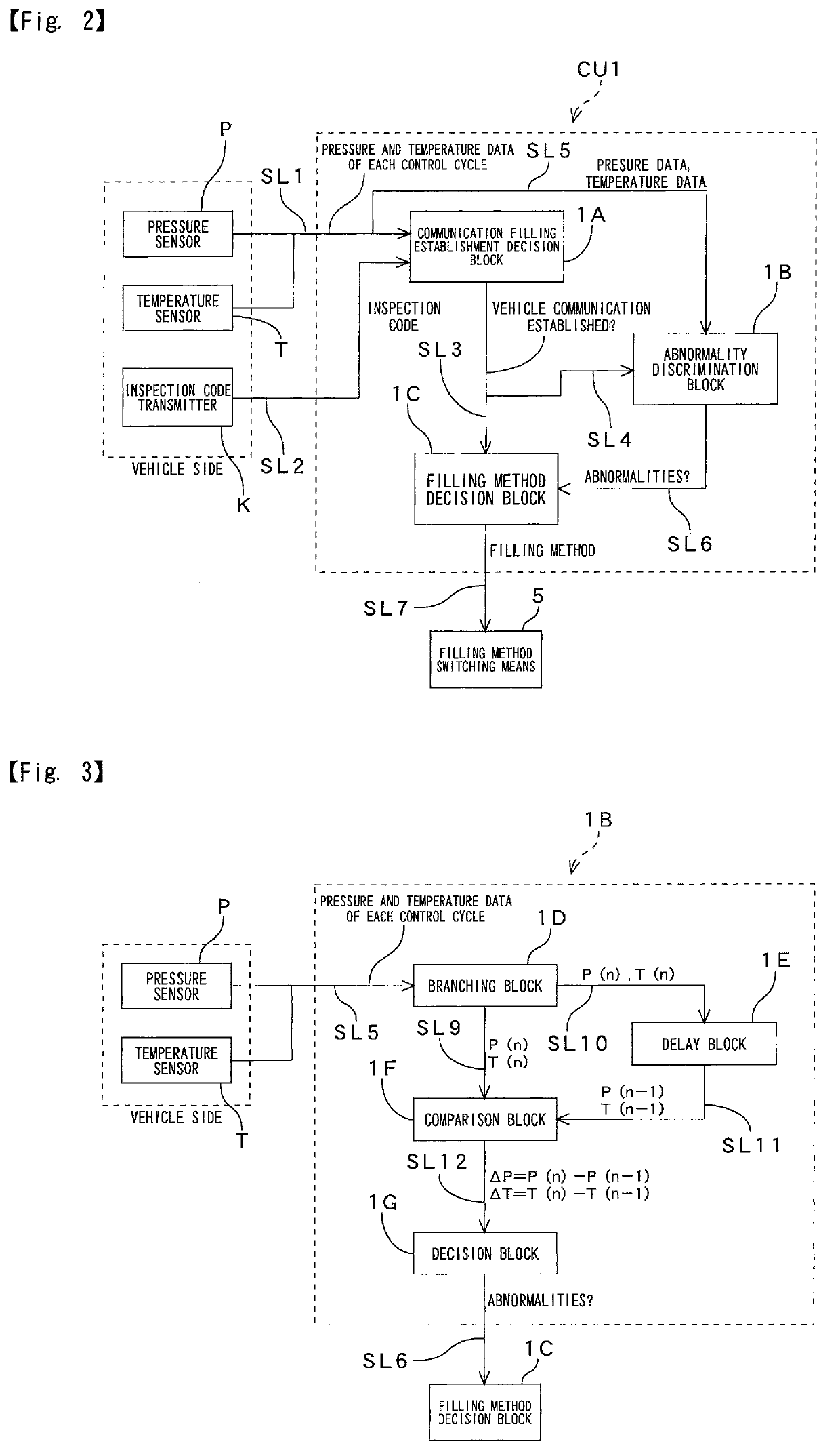
[0023]Next, embodiments of the present invention will be explained with reference to the drawings. At first, the present invention will be explained with reference to FIGS. 1 to 5. In FIG. 1, a hydrogen filling system of the present invention whose overall construction is indicated with numeral 100 includes a hydrogen filling device 1 and a control unit CU1 for controlling hydrogen filling, and the control unit CU1 is installed in the hydrogen filling device 1. To the hydrogen filling device 1 is connected a filling hose 2, and to an end of the filling hose 2 is attached a filling nozzle 3. The filling nozzle 3 is connectable and disconnectable to a receptacle SR on an in-vehicle tank IT (fuel tank) of a vehicle S to which hydrogen is filled (for instance, a fuel cell vehicle FCV). In addition, the hydrogen filling device 1 includes a signal transmitting system 4 for transmitting information on the in-vehicle tank of the S such as pressure and temperature data. The signal transmitti...

second embodiment

[0048]Next, with reference to FIG. 6, the present invention will be explained. In the hydrogen filling system 100-1 shown in FIG. 6, the control unit CU2 is mounted, not to each hydrogen filling device 1, but to a rear equipment 10. Here, the “rear equipment” includes so-called “POS” also in this specification. And, the rear equipment is mounted in an office for instance in a gas station. In FIG. 6, the rear equipment 10 is installed in an office of a gas station with plurality of hydrogen filling devices (dispensers) 1, and the control unit CU2 is mounted in the rear equipment 10. The control unit CU2 of the rear equipment 10 is connected to a plurality (three in FIG. 6) of hydrogen filling devices 1, 1-1, 1-2 through signal transmitting systems 11, 11-1, 11-2 capable of bidirectional communication such as optical communication path, and each hydrogen filling devices 1, 1-1, 1-2 is connectable to each in-vehicle tank IT, IT-1, IT-2 of each vehicle S, S-1, S-2 through a filling hose...


PUM


Abstract

To provide a hydrogen filling system and a hydrogen filling method capable of preventing hydrogen from being filled at high filling rate in the same manner as the communication filling despite a condition that pressure, temperature and so on in the in-vehicle tank are not precisely grasped. The hydrogen filling system (100) of the present invention includes a control unit (CU1, CU2, CU3) for controlling hydrogen filling, wherein the control unit has a function of judging whether or not there is an abnormality in pressure or temperature data in an in-vehicle tank (IT) at communication filling and a function of stopping the communication filling and converting to non-communication filling when there is an abnormality in the pressure or the temperature data.

Description

CROSS-REFERENCE TO RELATED APPLICATIONS[0001]The present application claims priority to Japanese Application No. 2019-004878 filed on Jan. 16, 2019, the disclosure of which is incorporated herein by reference.STATEMENT RE: FEDERALLY SPONSORED RESEARCH / DEVELOPMENT[0002]Not ApplicableBACKGROUND1. Technical Field of the Invention[0003]The present invention relates to a technique for filling hydrogen to hydrogen vehicles (FCVs) and so on.2. Description of the Related Art[0004]In recent years, accompanied by development and spread of vehicles mounting fuel cell (fuel cell vehicles, FCVs), it has been placed high importance to increase installation places of hydrogen station as hydrogen supply facility (refer to Patent document 1, for example). In the hydrogen station is mounted a hydrogen filling device (dispenser), which fills hydrogen to an in-vehicle tank of a vehicle arriving at the hydrogen station under the condition that pressure and temperature of the tank are maintained in prede...

Claims


Application Information

Patent Timeline
Patent Type & Authority Applications(United States)
IPC IPC(8): B67D7/32B67D7/04F17C13/02
CPCB67D7/04F17C13/025F17C13/026F17C2250/072F17C2221/012F17C2250/0439B67D7/3245F17C2250/043F17C2260/022F17C2265/065F17C5/06B60S5/02F17C2250/03F17C2270/0178F17C2250/034F17C2225/0123F17C2225/036F17C2223/0123F17C2223/036F17C2250/032F17C2250/0434F17C2250/0636F17C2250/07F17C2260/042F17C2260/024F17C2270/0184F17C2270/0168F17C2227/04Y02E60/32F17C5/007H04L41/0663F17C2270/0139
Inventor NATORI, NAOAKIYOSHIDA, YUICHI
Owner TOKYO TATSUNO CO LTD
Why Eureka
Try Eureka