Illumination apparatus for vehicle

a technology for illumination apparatus and vehicle, which is applied in the direction of lighting and heating apparatus, semiconductor devices for light sources, planar light sources, etc. it can solve the problems of increasing the cost of the illumination apparatus on the whole, limiting the design freedom of optical elements used in combination with the illumination module, and complicated wiring design of the circuit board, so as to reduce the cost, reduce the size, and reduce the effect of light emission efficiency

Inactive Publication Date: 2020-07-16
EVERLIGHT ELECTRONICS
View PDF0 Cites 2 Cited by
  • Summary
  • Abstract
  • Description
  • Claims
  • Application Information

AI Technical Summary

Benefits of technology

[0039]4. Because the LED chip and the driver chip are disposed within the same packaging structure, the LED package may have a smaller size overall, and may also reduce the cost. Moreover, if the driver chip has a temperature sensing function, the driver c

Problems solved by technology

Because illumination apparatuses usually use a plurality of packages of LED chips to emit light to provide sufficient luminance, and each package of LED chips needs to be connected to the respective driving element, the wiring design of the circuit board is quite complicated.
When the volume of the illumination module is large, the freedom of the design of the optical elements used in combination with the illumination module will also be restricted.
On the other hand, since the LED chip and the driving element are packaged separately (i.e., the package of the LED chip and the package of the driving element are manufactured independently and separate from each other), the LED chip and the driving element need to be purchased and stored individually, which inevitably inc

Method used


Image

  • Illumination apparatus for vehicle
  • Illumination apparatus for vehicle
  • Illumination apparatus for vehicle

Examples


Embodiment Construction

[0051]Specific embodiments of the present invention will be described specifically hereinafter. However, the present invention may be implemented with various different forms of embodiments without departing from the spirit of the present invention, and the scope claimed in the present invention should not be construed as being limited to what is described in the specification. Additionally, the technical contents of various implementations in the above summary of the invention may also serve as the technical contents of the embodiments or as possible variants of the embodiments. Moreover, the orientation described hereinafter (e.g., front, back, upper, lower, two sides or the like) are opposite orientations, and may be defined according to the use status of the illumination apparatus.

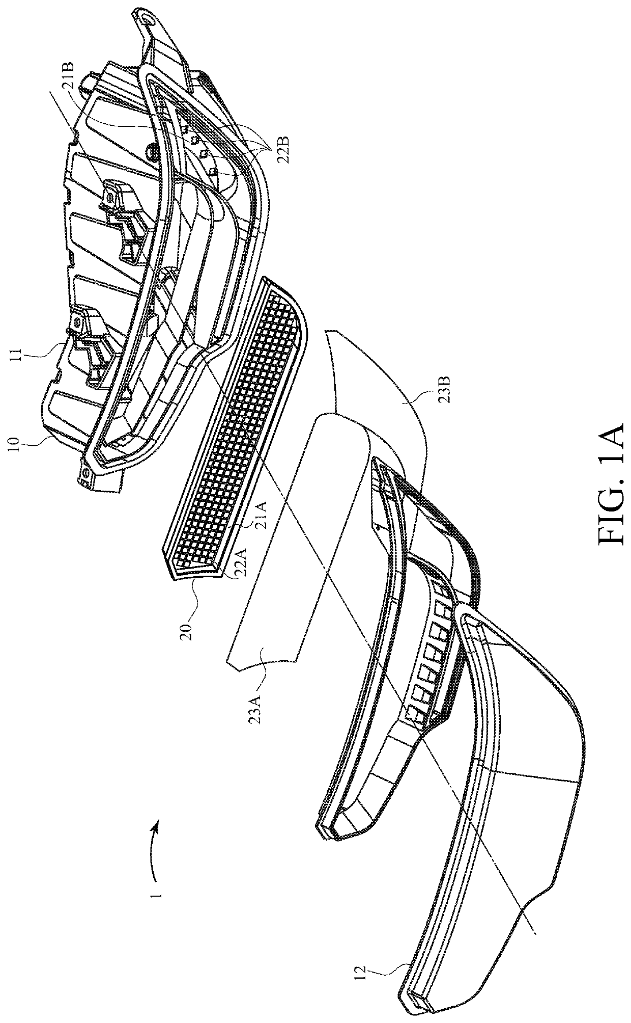
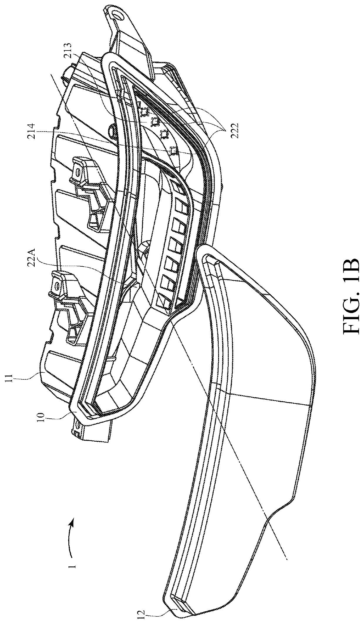
[0052]With reference to FIGS. 1A and 1B, which are perspective exploded views of an illumination apparatus 1 according to the preferred embodiment of the present invention. The illumination apparatus 1...


PUM


Abstract

An illumination apparatus for vehicle is disclosed, which includes an illumination module and a microcontroller. The illumination module includes a circuit base and an LED array which is disposed on the circuit base and includes a plurality of LED packages. Each of the LED packages includes a driver chip, a light source and a packaging structure, in which the driver chip and the light source are disposed. The driver chip is electrically connected to the light source to drive the light source to emit lights. The microcontroller is electrically connected to the LED packages to control the operation of the LED packages. Therefore, lights emitted from the LED packages can form a dynamic or static image; moreover, the light source (LED chip) and the driver chip are in the same packaging structure, so the circuit layout of the circuit base can be simplified.

Description

CROSS-REFERENCES TO RELATED APPLICATIONS[0001]This application claims priority to Taiwan Patent Application No. 108101433 filed on Jan. 11, 2019, which is hereby incorporated herein by reference in its entirety.BACKGROUND OF THE INVENTIONField of the Invention[0002]The present invention provides an illumination apparatus, and more particularly, an illumination apparatus for a vehicle.Descriptions of the Related Art[0003]Vehicles (such as automobiles or motorcycles) all have a plurality of illumination apparatuses which emit light to lighten roads or the like so that drivers can observe the roads clearly, thereby, improving driving safety. Moreover, the light emitted by the illumination apparatus can also indicate the behaviors of the vehicles, e.g., braking, turning, reversing or the like, so that other vehicles or pedestrians can observe and respond to these behaviors accordingly.[0004]More of the aforesaid illumination apparatuses for vehicles are utilizing light-emitting diode (L...

Claims


Application Information

Patent Timeline
IPC IPC(8): F21S43/14F21S43/19F21V23/00
CPCF21W2103/20F21S43/195F21W2103/45F21V23/003F21Y2105/16F21S43/14F21W2103/35F21W2107/10F21Y2115/10F21W2103/00H01L25/167H01L25/0753H01L33/62H05B45/44H05B47/155
Inventor LI, SHUN-CHANG
Owner EVERLIGHT ELECTRONICS
Why Eureka
Try Eureka