

Pass-thru window and orifice cap
a technology of orifice cap and window, which is applied in the field of life sciences manufacturing industry, can solve the problems of cost-effective manufacturing, and achieve the effects of convenient cleaning, simple yet versatile design, and convenient installation
- Summary
- Abstract
- Description
- Claims
- Application Information
AI Technical Summary
Benefits of technology
Problems solved by technology
Method used
Image

Examples
first embodiment
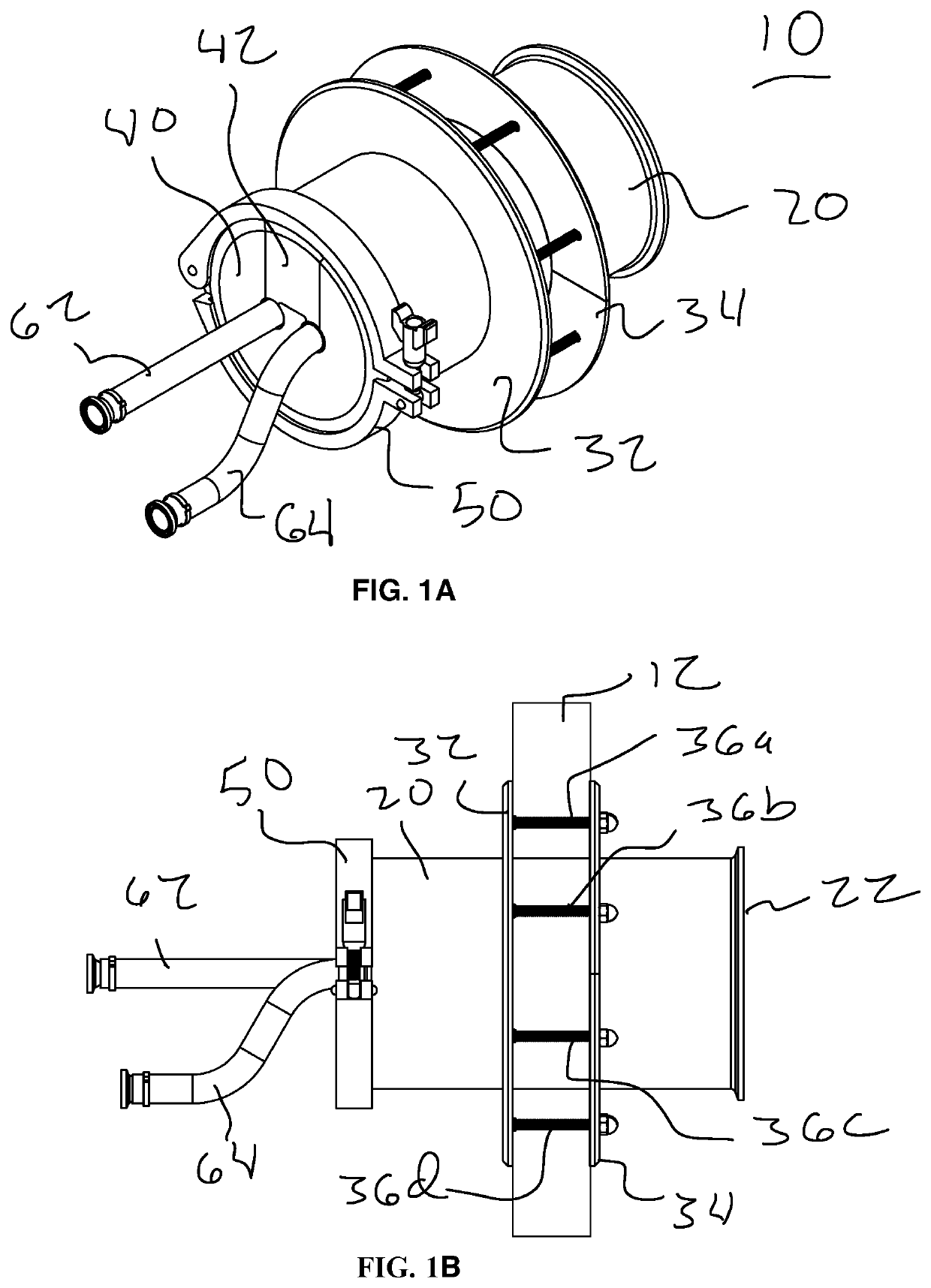
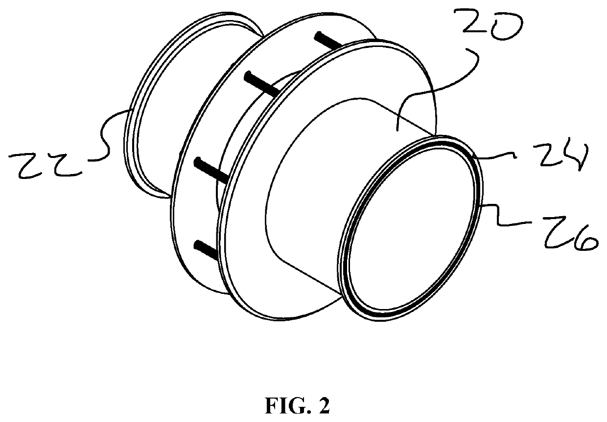
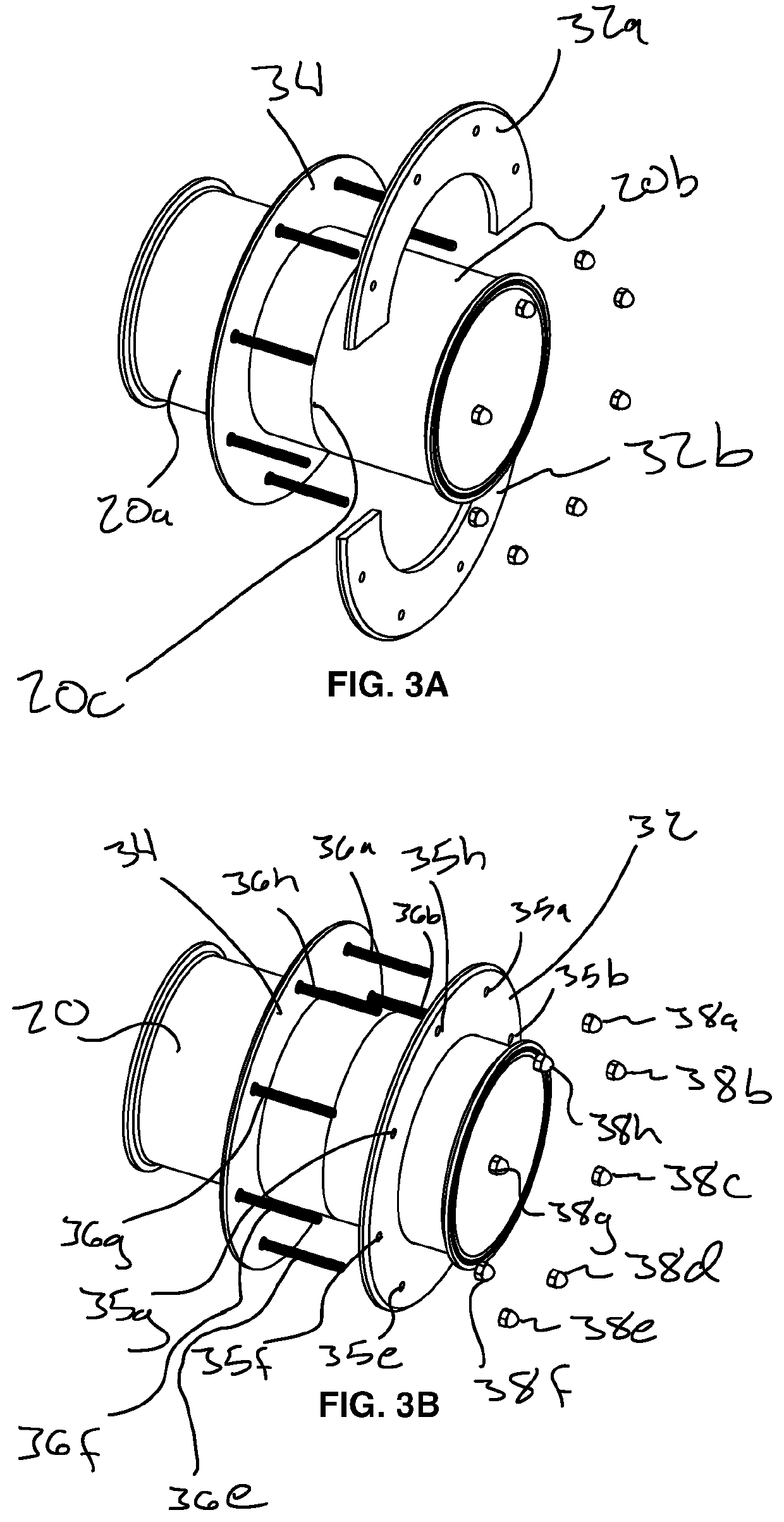
[0034]As seen in FIGS. 1-2, in general in a first embodiment, a pass-thru window system 10 is shown that typically includes a made-to-order sanitary tri-clamp spool, with a seamless or seamed flange 32, 34 at one side of the pass-thru to seal the thru-hole in the wall and a solid or split clamping flange for ease of installation located on the other side of the wall. The tri-clamp spools 20 are generally pre-fabricated lengths of tubing with tri-clamp fitting ends 22, 24. The spool 20 can be one or more pieces 20a, 20b, as seen in FIG. 3A, and may be assembled, welded, machined, bolted, or glue in place to form a “single” spool 20 at connection area 20c. The spool 20 can be compatible with standard tri-clamp end caps and gaskets for sealing the pass-thru when not in use, and alternatively can be made-to-order with a custom orifice cap for use with tubing, hoses, cables, and other types of conduits. The present invention can be compatible with the geometry of a standard tri-clamp fer...
embodiment 100
[0044]In an alternative embodiment 100, as shown in FIGS. 6A-6C, the assembly 100 can be substantially the same as the assembly 10 of FIG. 1, and only those pertinent differences will be discussed. The differences between assembly 100 and assembly 10 generally relate to the number of pass-through holes on the orifice cap. In the illustrated embodiment of FIGS. 6A-6C, only one through hole 149 is provided. As shown, the sliding gate 142 and the body 140 define a single through hole 149 when the sliding gate 142 is fully inserted into the body. The orifice cap 140 can be secured to the spool 120 by means of the same type of gasket 152 and clamp 150. In other embodiments, three or more through holes can be provided as needed by the end user.
[0045]In a further alternative embodiment 200, as shown in FIGS. 7A & 7B, instead of a single gate 42 of the embodiment 10, there can be two, or more, sliding gates 242a, 242b. Each of the two illustrated gates 242a, 242b can be inserted into respec...
embodiment 1100
[0053]As to the rectangular housing assembly seen in FIGS. 13A & 13B, the same options are available as found with the above embodiments. In this embodiment 1100, orifice caps are not used. Instead, single or multiple actuatable gates 1130a, 1130b can be controlled together or independently from one another so they may receive one or more tubes, cables or other conduit 1162, 1164, 1166 therethrough. One of the gate elements 1130a, 1130b may be stationary or they may both move. The gate elements 1130a, 1130b can be actuated by a lever 1132. The rectangular assembly 1100 can be configured for specific numbers of tube, cables, and the like, with specific sizes to accommodate the application and environment at hand. Further, the system can be design with split arrangement that could be replaced to accommodate different sizes and shapes, for example with the use of replaceable inserts 1142, 1144, 1146 which can be switched or replaced. Plastic, rubber, silicone or other materials inserts...
PUM
 Abstract
Description
Claims
Application Information