Board connection structure, board mounting method, and micro-led display
a technology of connecting structure and mounting method, which is applied in the direction of printed circuit manufacturing, printed circuit non-printed electric component association, printed circuit aspects, etc., can solve the problems of difficult mounting, limited distance between electrodes, and mounting boards, so as to reduce the distance between electrodes of electronic components, reduce the distance between electrodes, and facilitate the size limitation of electronic components.
- Summary
- Abstract
- Description
- Claims
- Application Information
AI Technical Summary
Benefits of technology
Problems solved by technology
Method used
Image
Examples
first embodiment
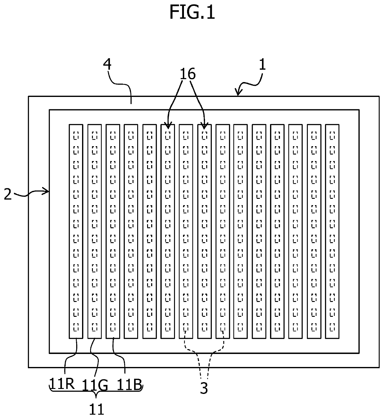
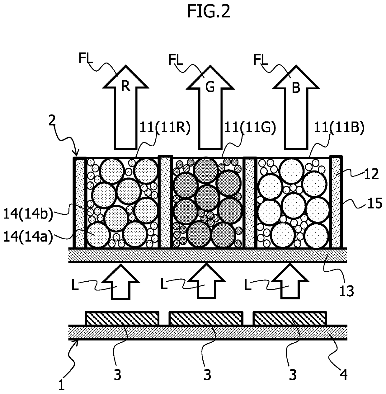
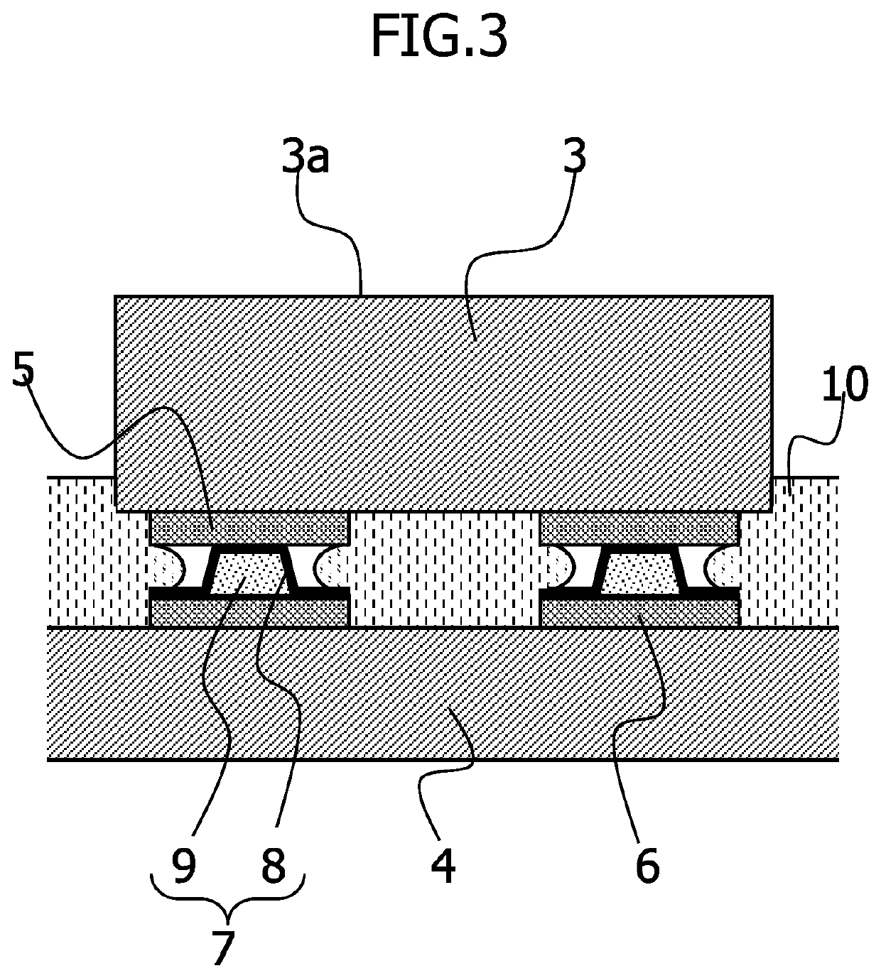
[0024]Hereinbelow, embodiments of the present invention will be described in detail with reference to the accompanying drawings. FIG. 1 is a plan view schematically showing a micro-LED display according to the present invention. FIG. 2 is an enlarged cross-sectional view of the main part of FIG. 1. FIG. 3 is a cross-sectional view schematically showing a board connection structure according to the present invention. The micro-LED display displays color images, and includes an LED array substrate 1 and a fluorescent layer array 2.
[0025]The LED array substrate 1 is provided with multiple micro LEDs 3, serving as electronic components, arranged in a matrix form, as shown in FIG. 1. The LED array substrate 1 has a structure in which the multiple micro LEDs 3 are arranged on a wiring board 4 that includes wiring for supplying an image signal to each micro LED 3 from a drive circuit provided externally, and that drives the micro LEDs 3 individually to be ON and OFF to turn on and off the ...
second embodiment
[0057]FIG. 7 is an enlarged cross-sectional view of the main part of the micro-LED display according to the present invention.
[0058]The second embodiment differs from the first embodiment in that the fluorescent layers 11 for red, green and blue colors, and the partition walls 12 are placed directly on the LED array substrate 1.
[0059]Next, the manufacture of the micro-LED display according to the second embodiment configured as described above will be described.
[0060]First, an LED array substrate 1 is manufactured in a manner similar to that in the first embodiment; multiple micro LEDs 3 emitting light in a near ultraviolet or blue wavelength band are arranged at predetermined positions on a wiring board 4 provided with wiring for driving the multiple micro LEDs 3, and each electrode 5 of the multiple LEDs 3 is electrically connected to a corresponding electrode pad 6 formed on the wiring board 4 through a conductive elastic protrusion 7.
[0061]Next, a transparent photosensitive resi...
third embodiment
[0068]FIG. 8 is an enlarged cross-sectional view of the main part of the micro-LED display according to the present invention.
[0069]The third embodiment is different from the first embodiment in that there is provided an excitation light blocking layer 17 that covers the fluorescent layers 11 for red, green and blue colors, and the partition walls 12, to block excitation light L. This excitation light blocking layer 17 selectively reflects or absorbs light in the same wavelength band as the excitation light L, contained in external light, such as sunlight, to prevent the fluorescent layers 11 from being excited by such light and from emitting light, so as to improve color reproduction.
[0070]Specifically, when the excitation light L is ultraviolet light, the excitation light blocking layer 17 is provided so as to cover the fluorescent layers 11 for red, green and blue colors, and the partition walls 12, as shown in FIG. 8. In a case in which the excitation light L is light in the blu...
PUM
| Property | Measurement | Unit |
|---|---|---|
| distance | aaaaa | aaaaa |
| wavelength | aaaaa | aaaaa |
| wavelength | aaaaa | aaaaa |
Abstract
Description
Claims
Application Information
 - R&D
- Intellectual Property
- Life Sciences
- Materials
- Tech Scout
- Unparalleled Data Quality
- Higher Quality Content
- 60% Fewer Hallucinations
Browse by: Latest US Patents, China's latest patents, Technical Efficacy Thesaurus, Application Domain, Technology Topic, Popular Technical Reports.
© 2025 PatSnap. All rights reserved.Legal|Privacy policy|Modern Slavery Act Transparency Statement|Sitemap|About US| Contact US: help@patsnap.com


