Cable recovery machine

a cable and machine technology, applied in the field of machine to recover cables, can solve the problems of known traction modules, process interruption, catastrophic fall of tensioned lines, etc., and achieve the effect of effectively absorbing shocks, preventing the pressure exerted during the passage of cables or joints, and preventing the passage of cables

Active Publication Date: 2020-08-13
TESMEC
View PDF23 Cites 15 Cited by
  • Summary
  • Abstract
  • Description
  • Claims
  • Application Information

AI Technical Summary

Benefits of technology

[0052]Advantageously, thanks to the use of one or more idle wheels cooperating with one or more traction wheels and able to exert a suitable pressure on the cable located between them and the traction wheels, it is possible to obtain a cable recovery machine in which the traction module is substantially able to adjust automatically and in particular in a passive manner whatever the external diameter or the thickness of the cable to be recovered, therefore able to adapt, automatically and without any external piloting system, even to passages of consecutive segments of cable with different diameters, as can occur on the cable, for example, in correspondence with a joint.
[0053]The present cable recovery machine is also able to effectively absorb the shocks generated by the passage of a joint or a sudden variation in the external diameter or thickness of the cable, keeping the pressure exerted during the passage of the cable or a joint almost constant.
[0054]The traction module can comprise at least one pair of idle wheels opposite at least one pair of traction wheels, so as to act on a segment of cable even more effectively and uniformly.
[0055]The traction module can comprise at least two pairs of traction wheels and at least two pairs of idle wheels, so as to provide an effective, uniform and simultaneous grip even on consecutive sections of cable with different diameters.

Problems solved by technology

The joints cannot pass over the winches, as they would break due to the bending caused by the winding on the circular surface, with the consequent catastrophic fall of the tensioned line.
Furthermore, the process is interrupted whenever the new conductor present at the brake station runs out, and therefore the empty reel needs to be replaced with a full one, or when the old conductor reel at the winch station is full, and therefore the full reel needs to be replaced with an empty one.
However, this known traction module has some disadvantages, particularly in relation to the need to adjust the amplitude of the passage space of the conductor which is defined between the motorized wheels.
Currently, this adjustment of the passage space is carried out by an external command which adjusts the reciprocal distance between the motorized wheels, therefore this adjustment is not carried out automatically and passively but requires suitable external piloting systems.
Furthermore, the known traction module does not allow to efficiently absorb the shocks normally generated by the passage of a joint or a sudden variation of the conductor section, therefore the pressure on the conductor is not kept constant.

Method used


Image

  • Cable recovery machine
  • Cable recovery machine
  • Cable recovery machine

Examples


Embodiment Construction

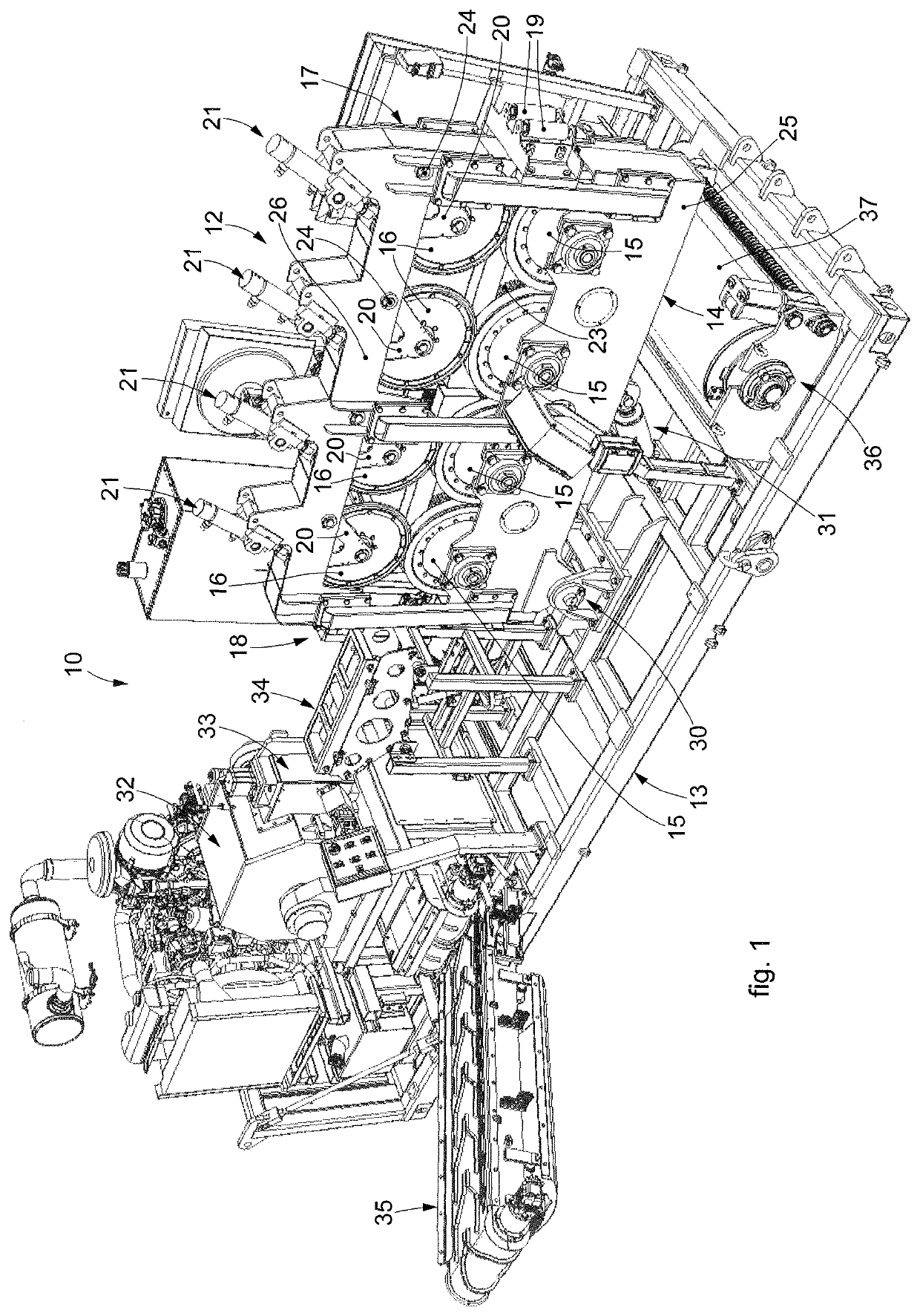
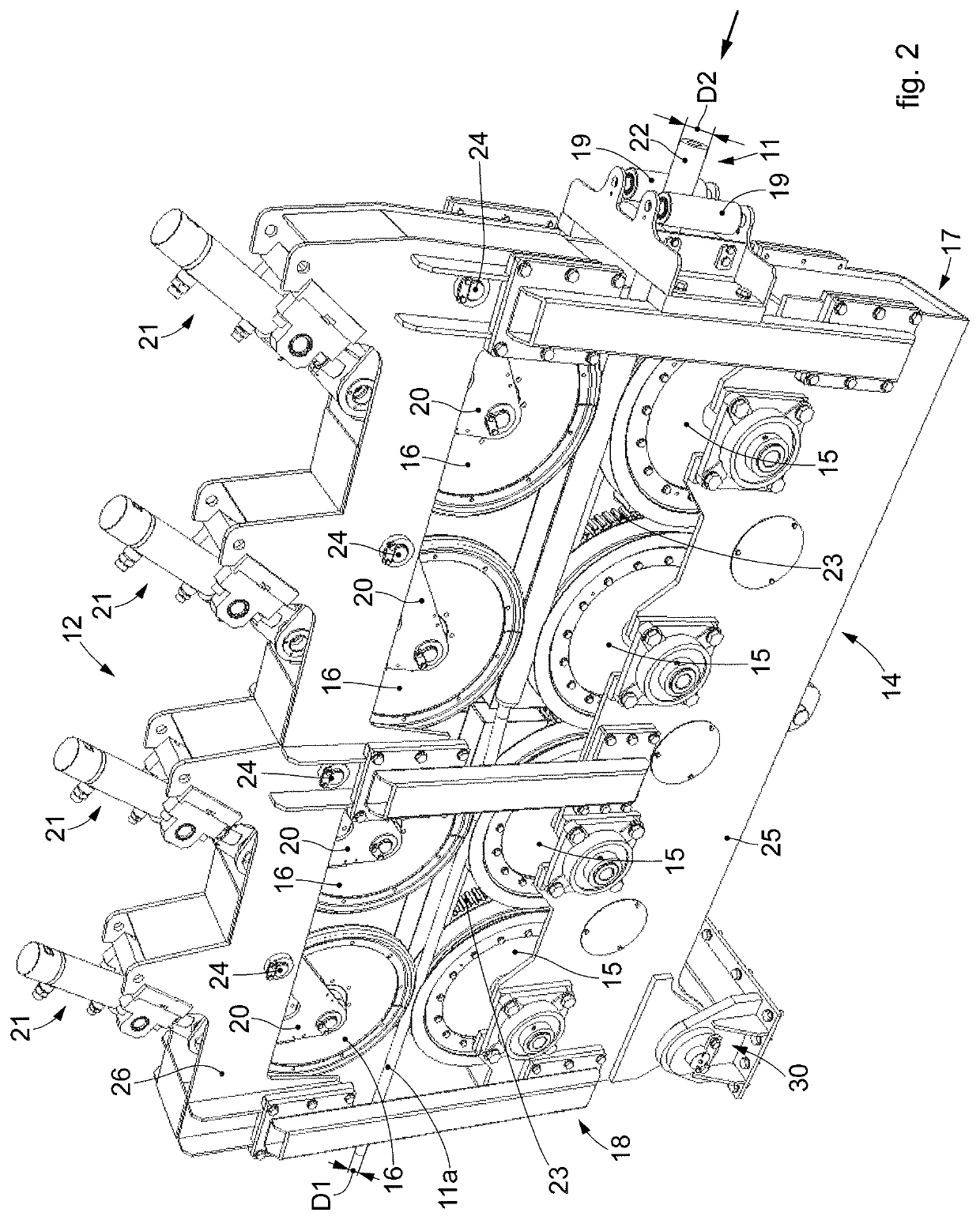
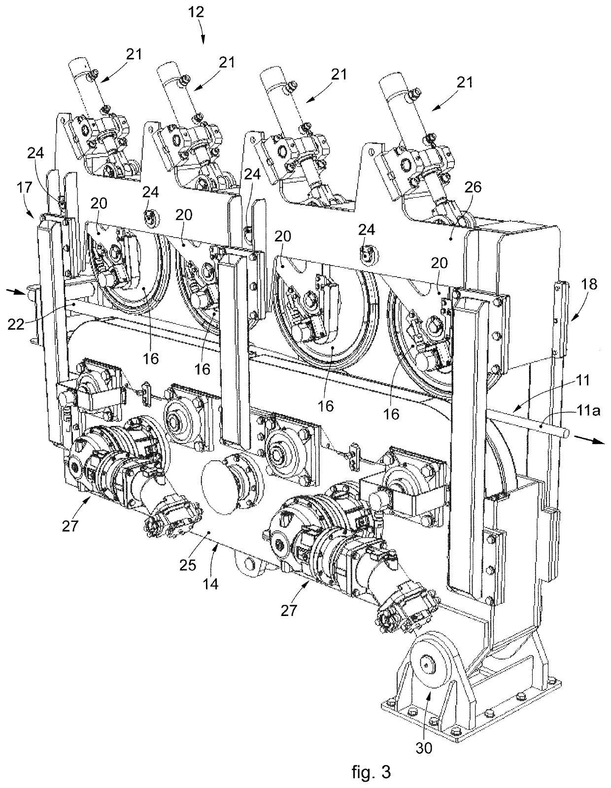
[0072]We will now refer in detail to the various embodiments of the present invention, of which one or more examples are shown in the attached drawings. Each example is supplied by way of illustration of the invention and shall not be understood as a limitation thereof. For example, the characteristics shown or described insomuch as they are part of one embodiment can be adopted on, or in association with, other embodiments to produce another embodiment. It is understood that the present invention shall include all such modifications and variants.

[0073]Before describing these embodiments, we must also clarify that the present description is not limited in its application to details of the construction and disposition of the components as described in the following description using the attached drawings. The present description can provide other embodiments and can be obtained or executed in various other ways. We must also clarify that the phraseology and terminology used here is f...


PUM

PropertyMeasurementUnit
lengthaaaaaaaaaa
diameteraaaaaaaaaa
thicknessaaaaaaaaaa

Abstract

A cable recovery machine, comprising at least one traction module configured to hold and draw at least one cable, in particular of a cable laying plant; the traction module comprises a frame on which one or more traction wheels and one or more idle wheels are positioned; between the traction wheels and the idle wheels a space is defined for the passage and traction of the cable to be recovered; the idle wheels are provided with a support connected in a mobile manner to the frame of the traction module and provided with actuators configured to press the idle wheels against the cable that passes between them and the traction wheels, so that the space between the idle wheels and the traction wheels can be automatically adjusted on the basis of the external diameter (D1, D2) or thickness of the cable drawn

Description

RELATED APPLICATIONS[0001]This application claims priority to Italy Patent Application No. 102019000001841, filed Feb. 8, 2019. This application is herein incorporated by reference in its entirety for all purposes.FIELD OF THE INVENTION[0002]The present invention concerns a machine to recover a cable, such as for example an electrical conductor, a wire, an optical fiber, or suchlike, in particular for the continuous recovery of a cable of a cable laying plant and for its disposal, for activities to replace the existing cable in the laying plant.[0003]The present recovery machine can be used in particular in a laying plant, for example, of a high voltage overhead electric line and in general in overhead lines which provide the commonly known “braked” laying of cables, that is of overhead conductors.BACKGROUND OF THE INVENTION[0004]In laying plants of overhead lines, the current method to replace overhead conductors, that is, so-called “reconductoring”, provides the following operatio...

Claims


Application Information

Patent Timeline
Patent Type & Authority Applications(United States)
IPC IPC(8): B65H75/44B65H51/06B65H75/42
CPCB65H2701/34B65H75/4442B65H75/425B65H75/4402B65H51/06B65H75/4457B65H2301/4189H02G1/04H02G1/005H02G1/1265B65H51/10Y02W30/82
Inventor OSCAR, ALBERTOPARODI, FABRIZIO
Owner TESMEC
Why Eureka
Try Eureka