Method and system for transflective display

Inactive Publication Date: 2020-08-13
SHARP KK
View PDF5 Cites 10 Cited by
  • Summary
  • Abstract
  • Description
  • Claims
  • Application Information

AI Technical Summary

Benefits of technology

[0005]The present invention relates to a transflective liquid crystal display (LCD) that can form an image using the same area of a sub-pixel to both reflect light (e.g., ambient lighting) and transmit light (e.g., from a backlight). An advantage of a transflective device is to enable better image quality and lower power consumption than a transmissive display when the displays are viewed in an environment with high ambient lighting, such as for example direct sunlight or

Problems solved by technology

The patterned reflector results in low efficiency because a significant amount of light emitted by the backlight is blocked.
Such a

Method used


Image

  • Method and system for transflective display
  • Method and system for transflective display
  • Method and system for transflective display

Examples


Embodiment Construction

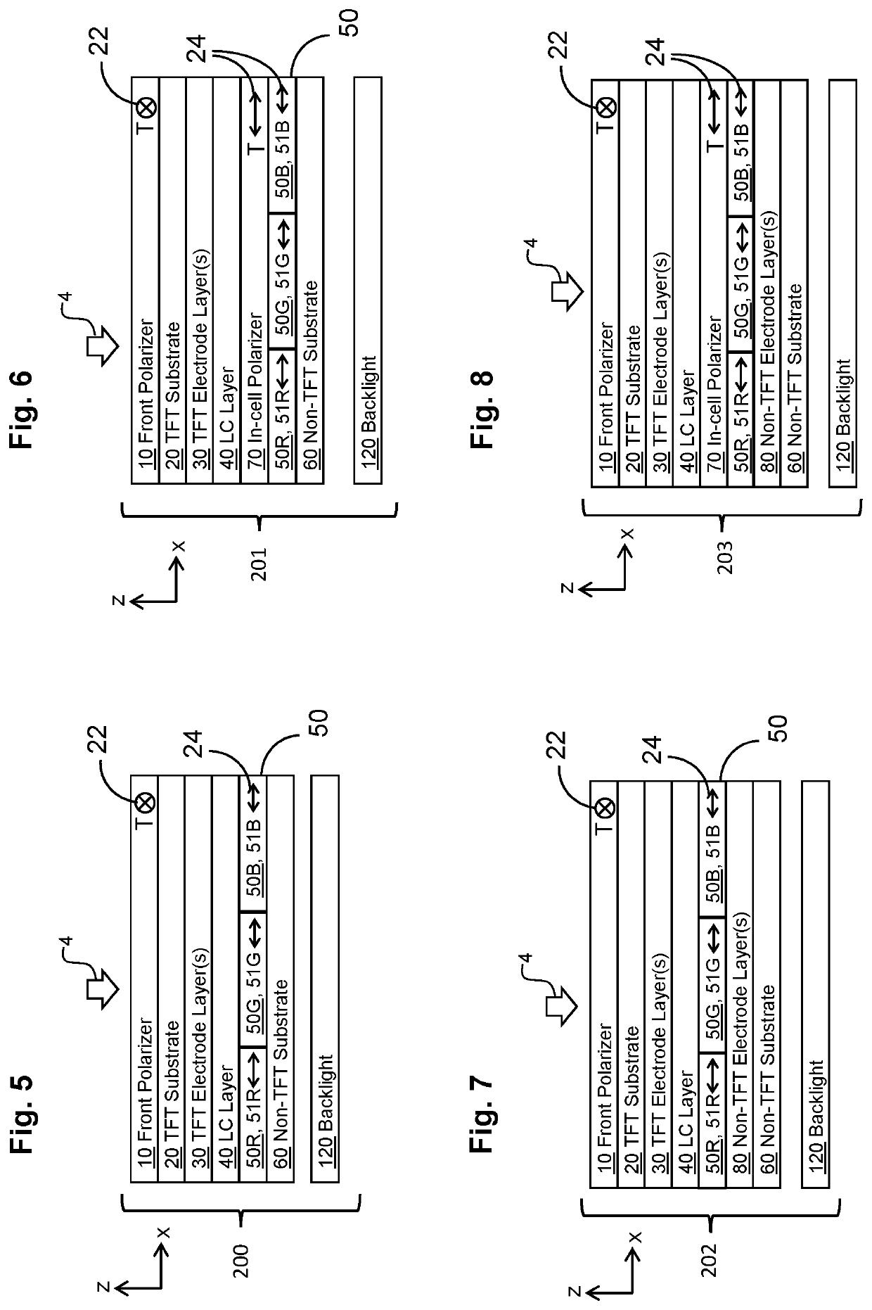
[0038]Embodiments of the present invention will now be described with reference to the drawings, wherein like reference numerals are used to refer to like elements throughout. It will be understood that the figures are not necessarily to scale.

[0039]In the drawings, each element with a reference number is similar to other elements with the same reference number independent of any letter designation following the reference number. In the text, a reference number with a specific letter designation following the reference number refers to the specific element with the number and letter designation and a reference number without a specific letter designation refers to all elements with the same reference number independent of any letter designation following the reference number in the drawings.

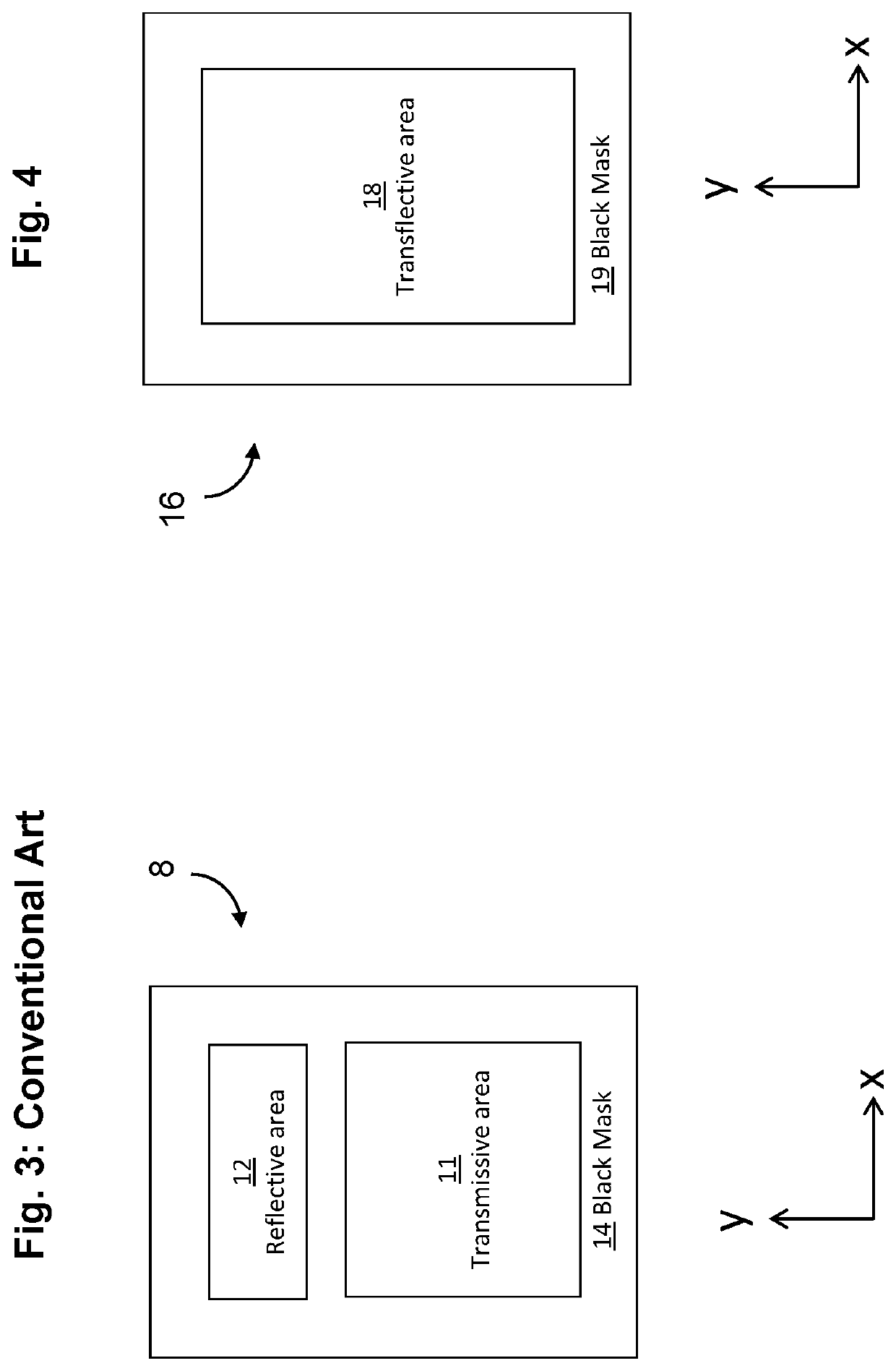
[0040]For illustrative purposes, FIG. 1 defines a coordinate system for illustrating pertinent terms of orientation used in this disclosure. The axes x, y and z are orthogonal to each other. The ...


PUM


Abstract

A transflective display has a viewing side and a non-viewing and includes a front polarizer with a transmission axis arranged in a first direction; a front substrate coupled to the non-viewing side of the front polarizer; a liquid crystal (LC) layer coupled to the non-viewing side of the front substrate; a quantum rod layer with one or more quantum rods aligned in a second direction, wherein the quantum rod layer is coupled to the non-viewing side of the LC layer; a rear substrate coupled to the non-viewing side of the quantum rod layer; and a backlight coupled to the non-viewing side of the quantum rod layer, wherein the quantum rod layer emits partially polarized light with a major axis substantially parallel (i.e. within ±15°) to the second direction. Each of the one or more quantum rods includes a long axis and a short axis, and the long axis is substantially parallel to the second direction.

Description

TECHNICAL FIELD[0001]The present disclosure relates generally to display devices and, more particularly, to transflective liquid crystal display devices using quantum rods.BACKGROUND ART[0002]Methods and systems using nanoparticles to improve the contrast ratio and brightness of a display have been used to enable better image quality. Conventional liquid crystal displays (LCDs), such as US 2016 / 0003998 (Benoit et al., published Jan. 7, 2016), may use an in-plane switching LC mode in combination with a Quantum Dot Enhancement Film (QDEF). US 2013 / 0335677 (You, published Dec. 19, 2013) describes the use of a blue backlight in combination with a QDEF sheet, a dichroic filter (to recycle blue light back to the QDEF sheet), and a conventional color filter. The QDEF sheet may contain a polymer host with a uniform mixture of quantum dots (Qdots) which converts a first portion of the blue light into red and green wavelengths. KR 20070094679 (Jiang et al.) describes an LCD which incorporates...

Claims


Application Information

Patent Timeline
IPC IPC(8): G02F1/1335G02F1/13363G02F1/1368G09G3/36G02F1/1337
CPCG02F1/1368G02F1/13363G09G2300/0452G02F1/133555G02F2203/09G09G3/3648G02F2001/133638G09G2300/0456G02F1/133536G02F1/1337G02F1/133617G02F1/133531G02F1/133638
Inventor SMITH, NATHAN JAMESACREMAN, ANDREW
Owner SHARP KK
Why Eureka
Try Eureka