Three-phase reactor comprising iron-core units and coils

a three-phase reactor and iron-core technology, applied in the direction of inductance, fixed transformers, cores/yokes, etc., can solve the problems of inability to ideally output imbalanced inductance, and inability to achieve a three-phase alternating current. , to achieve the effect of reducing the loss caused by a leakage flux

Active Publication Date: 2020-08-13
FANUC LTD
View PDF10 Cites 2 Cited by
  • Summary
  • Abstract
  • Description
  • Claims
  • Application Information

AI Technical Summary

Benefits of technology

[0006]In the three-phase reactors that are conventional (Japanese Unexamined Patent Publication (Kokai) No. 2-203507 and International Publication No. WO 2014 / 033830), the dimensions of gaps (thicknesses of gaps) depend on the dimensions of a commercially available gap member. Therefore, the winding number and cross-sectional area of a coil may be limited by the dimension of a gap member when the structure of a three-phase reactor is determined. The precision of inductances in a three-phase reactor depends on the precision of the thickness of a gap member. Because the precision of the thickness of a gap member is commonly around ±10%, the precision of inductances in a three-phase reactor also depends thereon. It is also possible to produce a gap member having a desired dimension while the cost of the gap member is increased.
[0007]In order to assemble a three-phase reactor, a step of assembling the core members of the three-phase reactor on a one-by-one basis, and a step of connecting some core members to each other are preferably performed several times. Therefore, there is a problem that it is difficult to control the dimension of a gap. In addition, a manufacturing cost is increased by improving the precision of the thickness of a gap member.
[0010]Further, the three-phase reactors that are conventional (Japanese Unexamined Patent Publication (Kokai) No. 2-203507 and International Publication No. WO 2014 / 033830) have a problem that a magnetic flux that has leaked out of a gap causes an eddy-current loss in a coil, thereby increasing the loss of the coil, because the coil is arranged close to the gap. A method of making a structure in which the coil is located away from the gap can be provided in order to solve the problem. However, the method has a demerit that a weight and a cost are increased because the core and the winding diameter of the coil become large.
[0012]Further, in the reactors having the conventional structures (Japanese Unexamined Patent Publication (Kokai) No. 2-203507 and International Publication No. WO 2014 / 033830), the temperatures of a coil and a core have tended to easily become unbalanced because of high thermal resistance between the coil and the core. In order to eliminate the unbalance between the temperatures, the entire coil may be molded with resin to bring the coil into intimate contact with the core. However, there is a problem that a cost is increased. Further, in order to suppress noise generated from a gap, design can be performed such that a magnetic flux density is reduced, and molding with resin can be performed as described above. However, there is also a problem that a cost is increased.
[0014]The present invention was accomplished under such circumstances with an object to provide a three-phase reactor with gaps, which inhibits inductances from being imbalanced and a magnetic field from leaking out to the outside, and in which a control winding is unnecessary, and a loss caused by a leakage flux can be reduced.

Problems solved by technology

Accordingly, there has been a problem that even when three-phase alternating currents in equilibrium are passed through the corresponding phases of a three-phase reactor, the densities of magnetic fluxes passing through iron cores in the corresponding phases are different from each other, and inductances are also imbalanced.
Therefore, magnetic fluxes generated from the iron-core coils cause imbalanced inductances.
When inductances are imbalanced in a three-phase reactor as described above, it is impossible to ideally output a three-phase alternating current even if the three-phase alternating current is ideally inputted.
In order to assemble a three-phase reactor, a step of assembling the core members of the three-phase reactor on a one-by-one basis, and a step of connecting some core members to each other are preferably performed several times. Therefore, there is a problem that it is difficult to control the dimension of a gap.
In addition, a manufacturing cost is increased by improving the precision of the thickness of a gap member.

Method used


Image

  • Three-phase reactor comprising iron-core units and coils
  • Three-phase reactor comprising iron-core units and coils
  • Three-phase reactor comprising iron-core units and coils

Examples


first embodiment

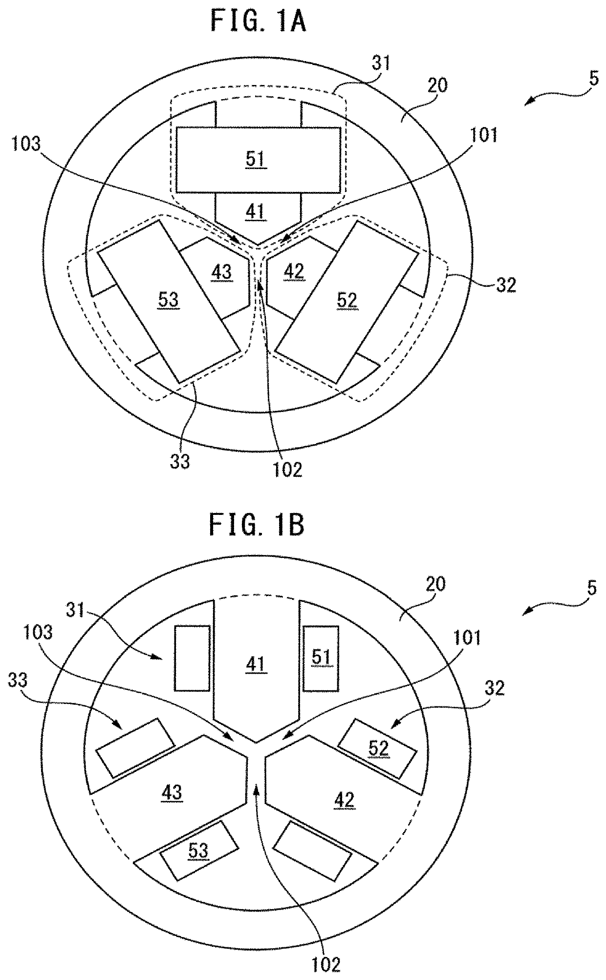
[0087]FIG. 1A is a top face view of a three-phase reactor according to the present invention. Further, FIG. 1B is a cross-sectional view of the three-phase reactor illustrated in FIG. 1A, and FIG. 1C is a perspective view of the three-phase reactor illustrated in FIG. 1A.

[0088]As illustrated in FIG. 1A, FIG. 1B, and FIG. 1C, a three-phase reactor 5 includes: an outer peripheral iron core 20; and three iron-core coils 31 to 33 of which each is magnetically connected to the outer peripheral iron core 20. In FIG. 1A, the iron-core coils 31 to 33 are arranged in the inside of the outer peripheral iron core 20 having a ring shape. The iron-core coils 31 to 33 are spaced from each other circumferentially at regular intervals in the three-phase reactor 5.

[0089]As can be seen from the drawings, the iron-core coils 31 to 33 include: corresponding iron cores 41 to 43 that radially extend; and corresponding coils 51 to 53 wound around the iron cores. The radially outer end of each of the iron ...

second embodiment

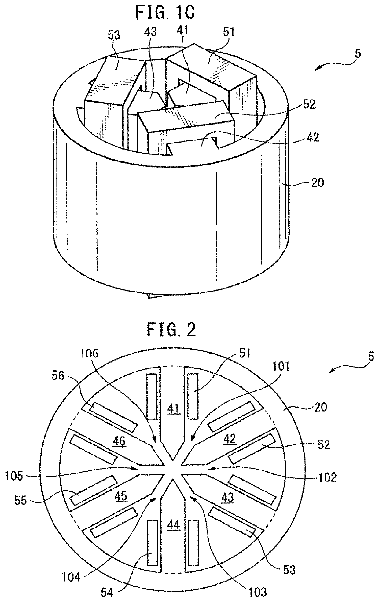
[0094]FIG. 2 is a cross-sectional view of a three-phase reactor according to the present invention. A three-phase reactor 5 illustrated in FIG. 2 includes: an outer peripheral iron core 20; and iron-core coils 31 to 36, each of which is magnetically connected to the outer peripheral iron core 20, and which are similar to those described above. The iron-core coils 31 to 36 include: corresponding iron cores 41 to 46 that radially extend; and corresponding coils 51 to 56 wound around the iron cores.

[0095]The front end angle of the radially inner end of each of the iron cores 41 to 46 of the three-phase reactor 5 illustrated in FIG. 2 is about 60 degrees. The radially inner ends of the iron cores 41 to 46 are spaced from each other through gaps 101 to 106 that can magnetically connect the radially inner ends to each other. As described above, the three-phase reactor 5 may include the iron-core coils 31 to 36 of which the number is a multiple of 3.

[0096]It is obvious that effects that ar...

third embodiment

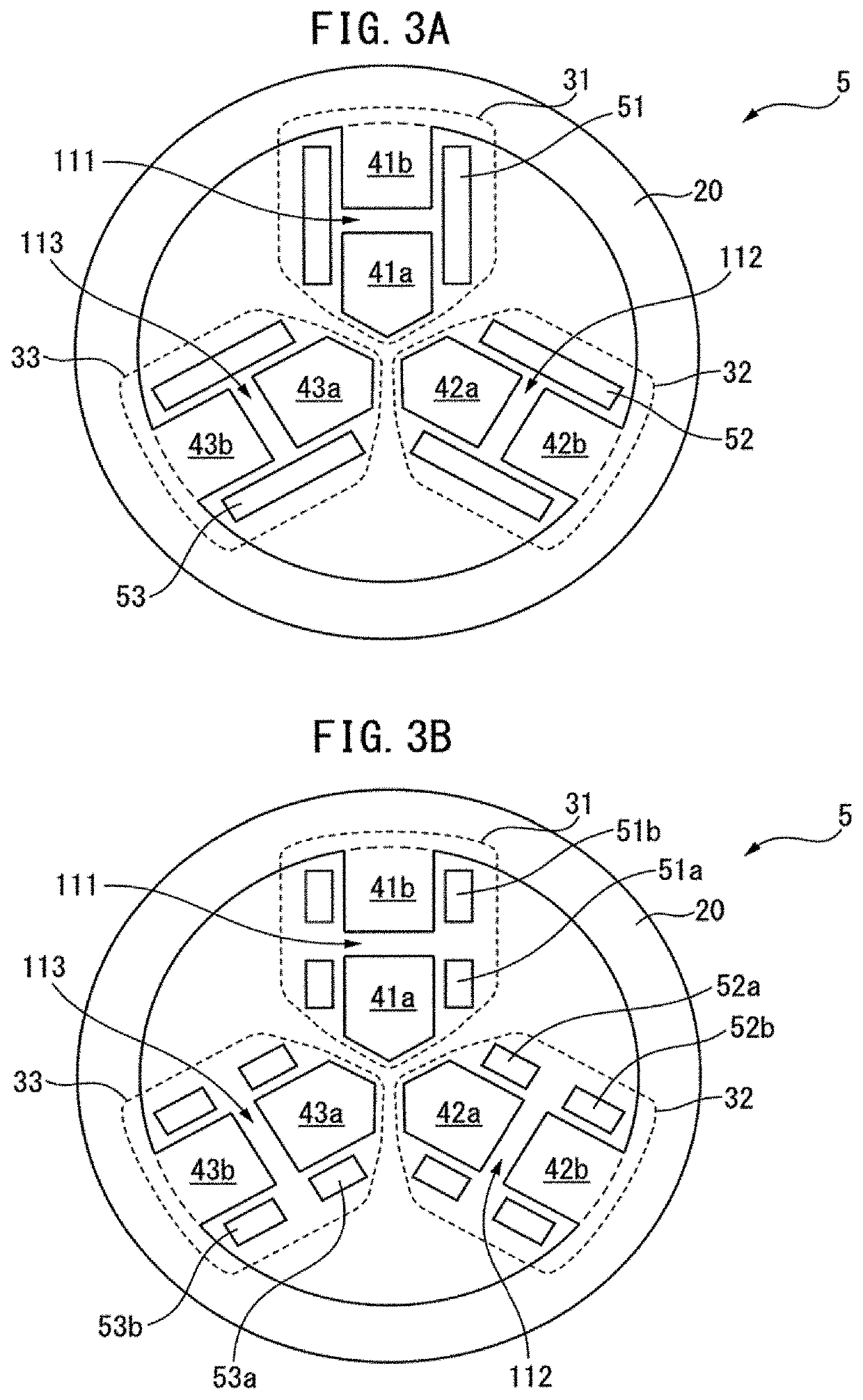
[0097]FIG. 3A is a cross-sectional view of a three-phase reactor according to the present invention. Iron cores 41 to 43 that radially extend in iron-core coils 31 to 33 in a three-phase reactor 5 illustrated in FIG. 3A include first iron-core units 41a to 43a that are located in radially internal sides, and second iron-core units 41b to 43b that are located in radially external sides, respectively. Iron-core unit gaps 111 to 113 that can magnetically connect the first iron-core units 41a to 43a and the second iron-core units 41b to 43b are formed between the first iron-core units 41a to 43a and the second iron-core units 41b to 43b. Further, the three-phase reactor 5 includes coils 51 to 53 that are wound around both the first iron-core units 41a to 43a and the second iron-core units 41b to 43b, respectively.

[0098]Further, FIG. 3B is a cross-sectional view of another three-phase reactor according to the third embodiment of the present invention. Iron cores 41 to 43 that radially ex...


PUM

PropertyMeasurementUnit
front end angleaaaaaaaaaa
magnetic flux densityaaaaaaaaaa

Abstract

A three-phase reactor includes: an outer peripheral iron core; and at least three iron-core coils that come in contact with an inner surface of the outer peripheral iron core or are joined to the inner surface. The at least three iron-core coils include corresponding iron cores and corresponding coils wound around the iron cores, and gaps that can magnetically connect one iron-core coil of the at least three iron-core coils and an iron-core coil adjacent to the one iron-core coil to each other are formed between the one iron-core coil of the at least three iron-core coils and the iron-core coil adjacent to the one iron-core coil.

Description

RELATED APPLICATIONS[0001]This application is a divisional of U.S. application Ser. No. 15 / 400,066, filed Jan. 6, 2017, which claims priority to Japanese Application No. 2016-160747, filed Aug. 18, 2016, and Japanese Application No. 2016-014484, filed Jan. 28, 2016, the teachings of which are herein incorporated by reference.BACKGROUND OF THE INVENTION1. Field of the Invention[0002]The present invention relates to a three-phase reactor including iron-core units and coils.2. Description of the Related Art[0003]Ordinarily, three-phase reactors include three iron cores and three coils wound around the iron cores. Japanese Unexamined Patent Publication (Kokai) No. 2-203507 discloses a three-phase reactor including three coils placed side by side. International Publication No. WO 2014 / 033830 discloses that the corresponding central axes of plural coils are arranged around the central axis of a three-phase reactor. Japanese Unexamined Patent Publication (Kokai) No. 2008-177500 discloses a...

Claims


Application Information

Patent Timeline
Patent Type & Authority Applications(United States)
IPC IPC(8): H01F37/00H01F27/32H02K11/33H01F3/14
CPCH01F37/005H01F37/00H02K11/33H01F3/14H01F27/324H01F27/263H01F27/2828H01F29/00H01F30/12
Inventor SHIROUZU, MASATOMOMAEDA, TAKUYA
Owner FANUC LTD
Why Eureka
Try Eureka