Method for performing metal injection with counter pressure

a metal injection and counter pressure technology, applied in metal-working apparatuses, transportation and packaging, etc., can solve problems such as shrinkage and warpage deformation, and achieve the effect of improving shrinkage unevenness and improving tensile strength

Inactive Publication Date: 2020-08-20
CHUNG YUAN CHRISTIAN UNIVERSITY
View PDF0 Cites 0 Cited by
  • Summary
  • Abstract
  • Description
  • Claims
  • Application Information

AI Technical Summary

Benefits of technology

[0004]In view of the disadvantages of prior art, the primary object of the present invention is to provide a metal injection system and method capable of applying a gas counter pressure onto its feedstock, such that not only is the feedstock compacted during feeding for improving tensile strength, but also the metal powders are enabled to be distributed uniformly in the feedstock so as to improve the uneven shrinkage problem caused during sintering.
[0011]enabling a green part to be molded in a manner that the particles are fed into a melting module for melting the particles into a melted flow that is guided to flow into a mold module while having a counter pressure module to apply a counter gas with a predetermined pressure to the mold module during the molding of the green part.
[0012]To sum up, during the molding of the green part by the use of the system and method of the present invention, the density of the green part is increased when there is a counter gas with the predetermined pressure being applied to the green part. In addition, not only is the feedstock compacted by the pressure of the counter gas and thus the tensile strength is enhanced, but also the metal powders in the feedstock are enabled to be distributed uniformly so that the uneven shrinkage problem caused during sintering is improved.

Problems solved by technology

As with other injection molding processes and products, MIM also has its own set of disadvantages, including warpage deformation and shrinkage problems.

Method used


Image

  • Method for performing metal injection with counter pressure
  • Method for performing metal injection with counter pressure
  • Method for performing metal injection with counter pressure

Examples


Embodiment Construction

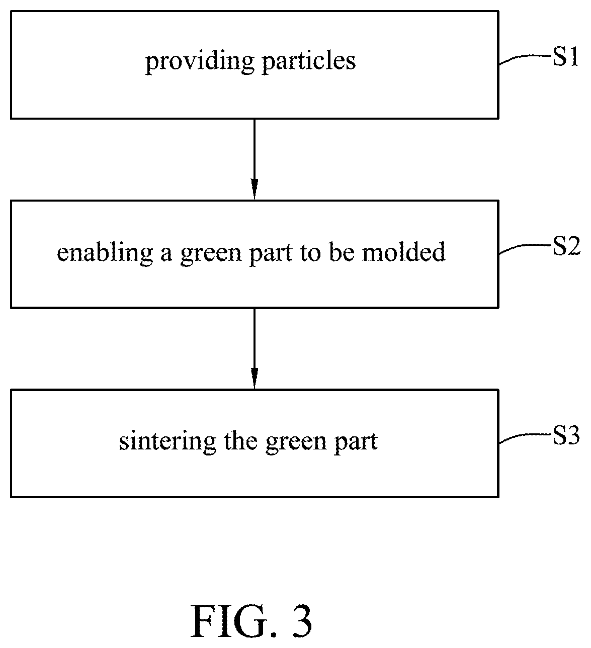
[0021]For your esteemed members of reviewing committee to further understand and recognize the fulfilled functions and structural characteristics of the invention, several exemplary embodiments cooperating with detailed description are presented as the follows.

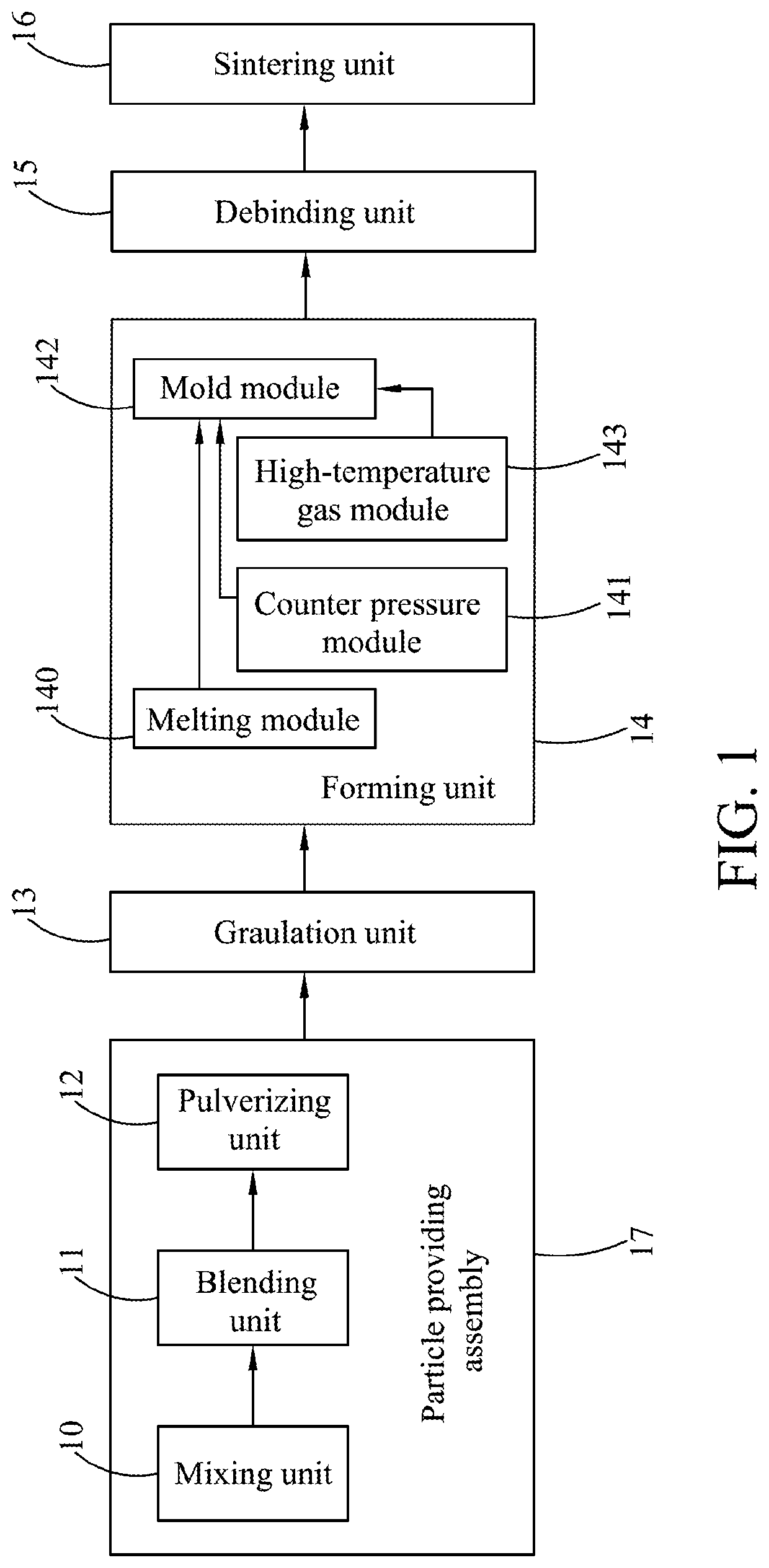
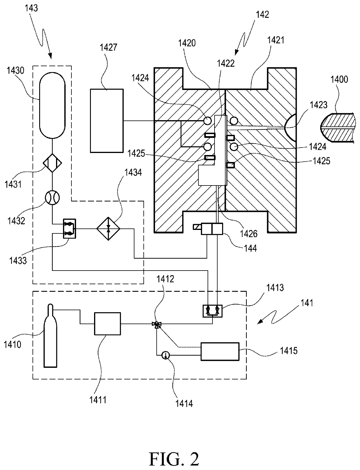
[0022]Please refer to FIG. 1, which is a schematic diagram showing a system for metal injection and counter pressure according to an embodiment of the present invention. In FIG. 1, a system for metal injection and counter pressure comprises: a mixing unit 10, a blending unit 11, a pulverizing unit 12, a granulation unit 13, a forming unit 14, a debinding unit 15, and a sintering unit 16.

[0023]The mixing unit 10 is used for mixing metal particles with a binding agent into a mixture. In this embodiment, the binding agent can be a mixture of paraffin and a polymer material or a polymer material, in which the polymer material can be polypropylene (PP). In addition, the amount of the metal particles in the mixture is about 50%˜70%,...


PUM

PropertyMeasurementUnit
pressureaaaaaaaaaa
pressureaaaaaaaaaa
temperatureaaaaaaaaaa

Abstract

A system for metal injection and counter pressure has: a particle providing assembly; and a forming unit having a melting module, a counter pressure module and a mold module; wherein, the particle providing assembly provides particles with metal powder and a binding agent to the melting module, the particles are formed into melted flow by the melting module, the melted flow is provided to the mold module, the counter pressure module provides a counter gas with predetermined pressure to the mold module, the melted flow forms into a green part inside of the mold module.

Description

FIELD OF THE INVENTION[0001]The present invention relates to a system for metal injection and counter pressure and method using the same, and more particularly, to a system and method capable of applying a gas counter pressure onto its metallic injection material, as known as “feedstock”, for enabling the metal powder to be distributed uniformly so as to increase tensile strength while improving uneven shrinkage during sintering.BACKGROUND OF THE INVENTION[0002]Metal injection molding (MIM) offers a manufacturing capability for producing complex shapes in large quantities. The process utilizes fine metal powders which are custom formulated with a binder (various thermoplastics, waxes, and other materials) into a feedstock which is granulated and then fed into a cavity (or multiple cavities) of a conventional injection molding machine. After the “green” component is removed, most of the binder is extracted by thermal or solvent processing and the rest is removed as the component is s...

Claims


Application Information

Patent Timeline
Patent Type & Authority Applications(United States)
IPC IPC(8): B22F3/22B22F3/10
CPCB22F3/1021B22F2998/10B22F3/225B22F1/108B22F9/04B22F1/148B22F1/102B22F3/1025
Inventor CHEN, SHIA-CHUNGCHANG, JEN-ANCHANG, YUNG-HSIANGLEE, KUAN-HUA
Owner CHUNG YUAN CHRISTIAN UNIVERSITY
Why Eureka
Try Eureka