Thermoelectric dehumidifying device

a dehumidifying device and thermoelectric technology, applied in space heating and ventilation, lighting and heating apparatus, heating types, etc., can solve the problems of inability to further cool the cold surface, inability to meet the needs of cramped use environments, and bulky dehumidifiers, so as to improve the dehumidification effect of the airflow entering the dehumidifying device, the effect of dehumidification capability

Inactive Publication Date: 2020-08-27
NORM PACIFIC AUTOMATION
View PDF0 Cites 5 Cited by
  • Summary
  • Abstract
  • Description
  • Claims
  • Application Information

AI Technical Summary

Benefits of technology

[0006]In view of the above, one aspect of the present invention is to provide a thermoelectric dehumidifying device, which is a slim cuboid with the air inlet / outlet provided on the short lateral surface of the case, and therefore is adapted to be placed in a cramped space for dehumidification. By providing the fan at a right position, the heat dissipation effect of the hot surface of the thermoelectric element could be improved, so that the temperature at the cold surface could be well-maintained to provide a better dehumidifying capability. Furthermore, the bottom of each condensing fin is inclined downward in line with the flowing direction of the airflow, and the bottoms of any two adjacent condensing fins are not at the same height, so that the sliding and dropping of the water droplets condensed on the condensing fins could be accelerated, which could improve the efficiency for the water droplets on the condensing fins to fall off. As a result, the overall dehumidifying efficiency of the thermoelectric dehumidifying device could be further enhanced.
[0008]By utilizing the difference between the horizontal lengths of the opposite lateral surfaces of the case and the first spacing between the opposite lateral surfaces, and by providing the air outlet and inlets between the first spacing, the thermoelectric dehumidifying device could be a slim cuboid, and therefore is adapted to be placed in a cramped space for dehumidification. Furthermore, the fan provided between the second air inlet and the heatsink could push the turbulent airflow, which is mixed by the outside airflow and the dehumidified cold airflow, to flow between the heat dissipation fins, which could effectively bring away the heat energy on the heat dissipation fins and the hot surface of the thermoelectric cooling module, whereby to maintain the low temperature at the condensing fins and to ensure the dehumidifying capability achieved by condensing water droplets. In addition, the bottom side of each of the condensing fins is designed to be inclined downward in line with the flowing direction of the airflow, which could urge the water droplets condensed on each of the condensing fins to slide in the downwardly inclined direction. Moreover, a droplet could easily contact and combine with another droplet condensed on the same or the adjacent condensing fin to form a more massive droplet, whereby the dropping of water droplets could be sped up. Therefore, the dehumidifying effect for the airflow which enters the dehumidifying device could be improved.

Problems solved by technology

However, this kind of dehumidifiers is usually bulky since it has to accommodate at least a gas compressor, a condenser, and an evaporator within, and therefore is not suitable for cramped usage environments such as in wardrobes, closets, or shoe cabinets.
Due to this reason, when the cold surface and the hot surface have a great temperature difference in between, the cold surface may not be able to be further cooled since only limited heat energy can be transferred to the hot surface.
As a result, the cold surface naturally has a poorer performance in condensing moisture.
However, when such mixed airflow passes by the hot surface, only the heat energy at locations on the hot surface having contact with the cross-section of the mixed airflow can be taken away, so that the heat dissipation effect of the hot surface is still rather limited.
If the heat dissipation effect of the hot surface is limited, so is the cooling effect of the cold surface of the thermoelectric cooling module, leading to a poor moisture-condensing performance on the cold surface, which hinders the dehumidifying efficiency.
However, those water droplets prevent the airflow from contacting the portions of the fins which are directly covered by the droplets, which hinders the cooling of the airflow, and therefore interferes with the water droplet from further condensing on the fins 23.
As a result, the dehumidifying efficiency of the airflow drawn into the dehumidifier is still not satisfying.

Method used


Image

  • Thermoelectric dehumidifying device
  • Thermoelectric dehumidifying device
  • Thermoelectric dehumidifying device

Examples


Embodiment Construction

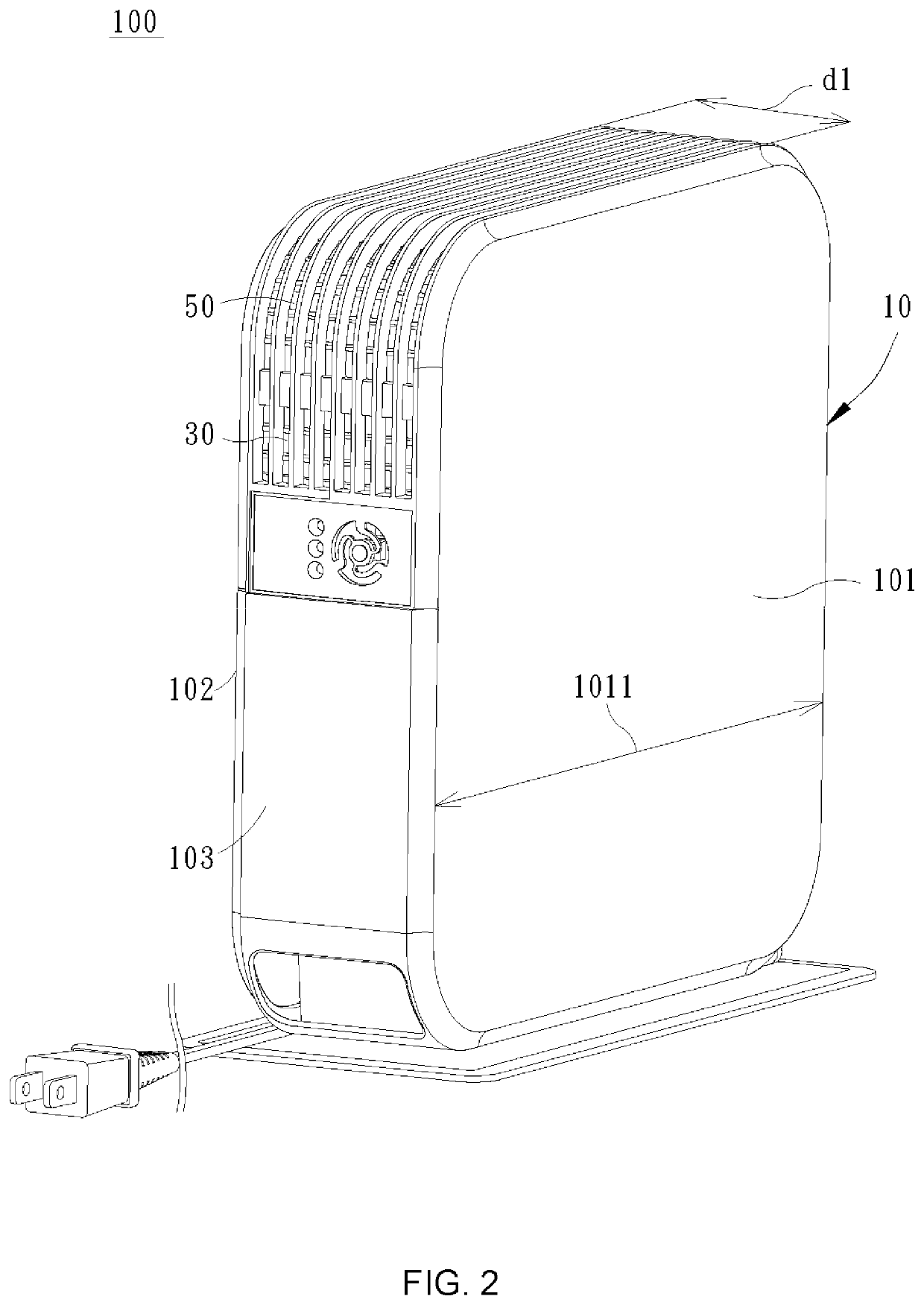
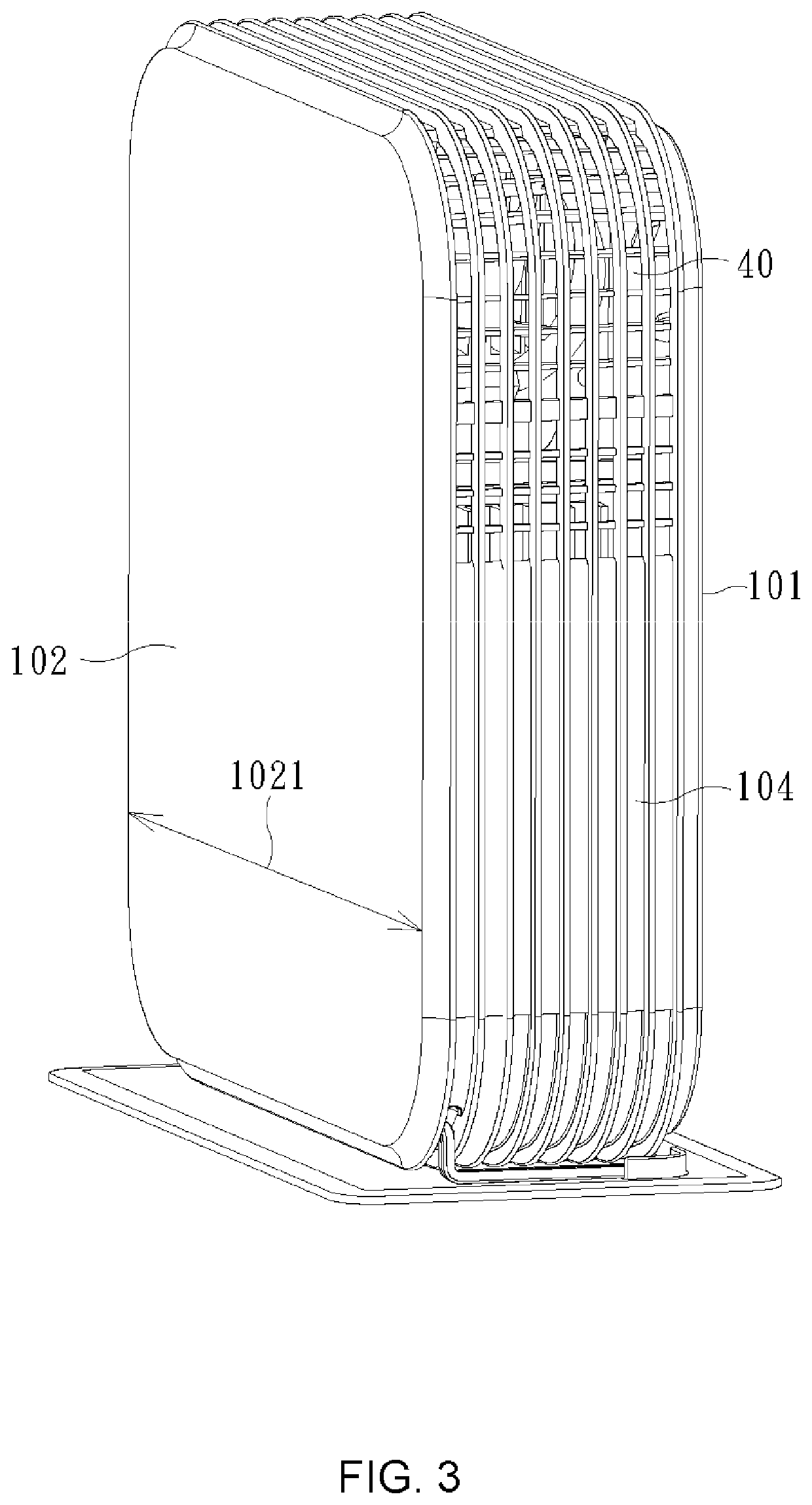
[0022]As shown in FIG. 2 toFIG. 8, a thermoelectric dehumidifying device 100 of the present invention includes a case 10, a thermoelectric element 20, a first air inlet 30, a second air inlet 40, an air outlet 50, a condenser 60, a heatsink 70, and a fan 80, wherein the first air inlet 30, the second air inlet 40, and the air outlet 50 are provided on the case 10, while the thermoelectric element 20, the condenser 60, the heatsink 70, and the fan 80 are provided in the case 10.

[0023]The case 10 includes a first lateral surface 101, a second lateral surface 102, a third lateral surface 103, and a fourth lateral surface 104, wherein the first lateral surface 101 and the second lateral surface 102 are separated by a first spacing d1. A horizontal length 1011 of the first lateral surface 101 and a horizontal length 1021 of the second lateral surface 102 are both greater than the first spacing d1. The third lateral surface 103 and the fourth lateral surface 104 are provided between the f...


PUM


Abstract

A thermoelectric dehumidifying device includes a case, on which a first air inlet, a second air inlet, and an air outlet are provided, and in which a thermoelectric element, a condenser, a heatsink, and a fan are provided. The thermoelectric element has a cold surface, to which the condenser is connected, and a hot surface, to which the heatsink is connected. The fan is provided between the second air inlet and the heatsink. Airflow flowing through the condenser will be cooled and dehumidified. Each fin of the condenser has a downwardly inclined bottom side, which facilitates the dripping of the water droplets condensed thereon. Said airflow will be mixed with external airflow drawn in through the second air inlet, and then blown by the fan to flow through fins of the heatsink, bringing away heat effectively and therefore improving the dehumidifying efficiency of the device.

Description

BACKGROUND OF THE INVENTION1. Field of the Invention[0001]The present invention relates generally to a thermoelectric dehumidifying device, and more particularly to a slim type thermoelectric dehumidifying device which has higher dehumidifying efficiency compared to conventional thermoelectric dehumidifying devices.2. Description of the Prior Art[0002]A conventional dehumidifier typically uses a gas compressor to circulate refrigerant in tube passes involving a condenser and an evaporator. Due to the change in pressure, the refrigerant circulating in tube passes undergoes phase transitions between a liquid state and a gaseous state. Specifically, at the evaporator section, the refrigerant changes from a liquid state to a gaseous state through evaporation. By absorbing the heat contained within, the evaporation of the refrigerant cools the surrounding air which is drawn into the dehumidifier and flows by the outside of the tube passes. As the air temperature decreases, the moisture i...

Claims


Application Information

Patent Timeline
Patent Type & Authority Applications(United States)
IPC IPC(8): F24F5/00F24F3/14F24F13/22
CPCF24F13/222F24F5/0042F24F3/14F24F2003/1446F24F13/20F24F2013/205
Inventor HUANG, HORNG-TSANNWENG, WEN-YU
Owner NORM PACIFIC AUTOMATION
Why Eureka
Try Eureka