Motor control device, electrically driven actuator product, and electrically driven power steering device
a technology of motor control device and actuator, which is applied in the direction of electric generator control, dynamo-electric converter control, dynamo-electric gear control, etc., to achieve the effect of reducing the torque of the motor
- Summary
- Abstract
- Description
- Claims
- Application Information
AI Technical Summary
Benefits of technology
Problems solved by technology
Method used
Image

Examples
first embodiment
Configuration
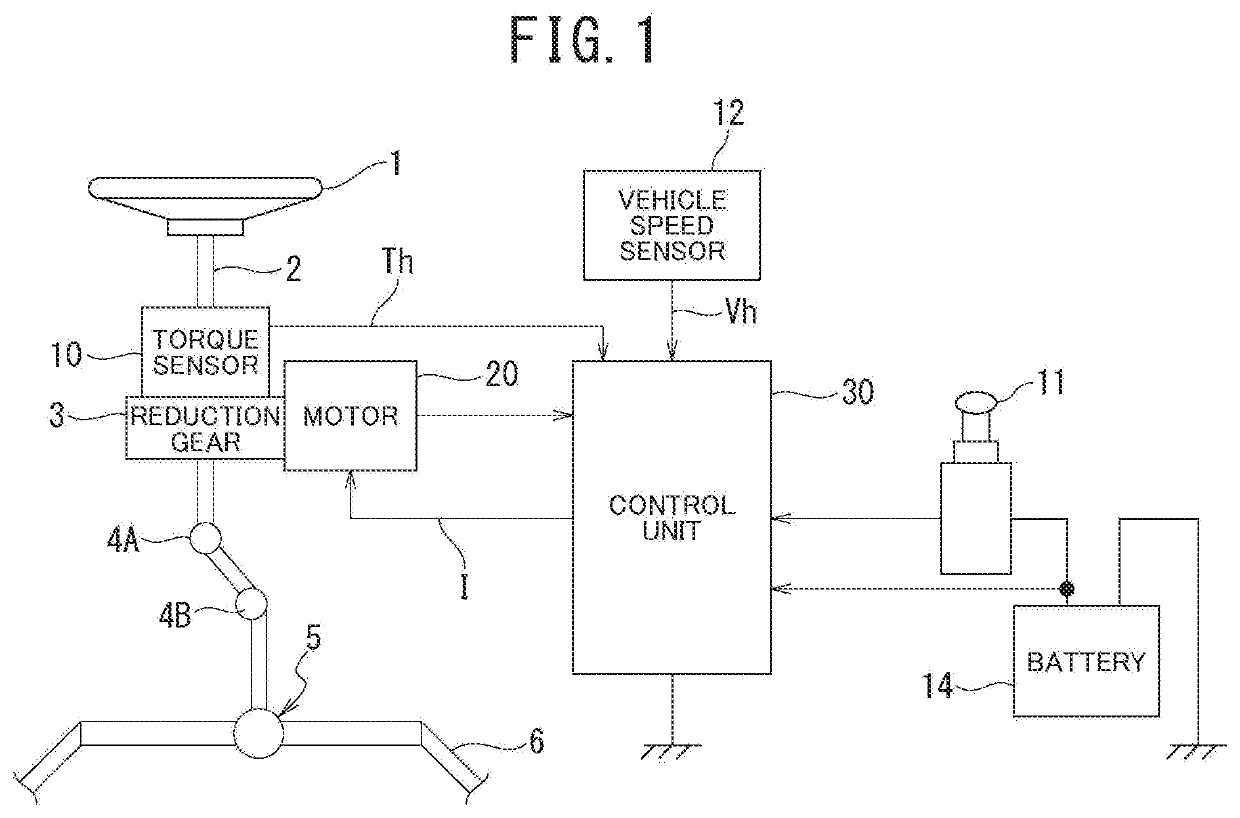
[0020]A configuration example of an electrically driven power steering device of an embodiment is illustrated in FIG. 1. A column shaft 2 of a steering wheel 1 is joined to a tie rod 6 connecting steered wheels via a reduction gear 3, universal joints 4A and 4B, and a rack-and-pinion mechanism 5. To the column shaft 2, a torque sensor 10 configured to detect steering torque applied to the steering wheel 1 is disposed, and a motor 20 configured to assist steering force of the steering wheel 1 is joined to the column shaft 2 via the reduction gear 3.
[0021]To a control unit (ECU) 30 configured to control the power steering device, power is supplied from a battery 14 that is a power supply and, in conjunction therewith, an ignition key signal is input from an ignition key 11, and the control unit 30 performs, based on steering torque Th detected by the torque sensor 10 and vehicle speed Vh detected by a vehicle speed sensor 12, calculation of a steering assist command value...
embodiment
Action of Embodiment
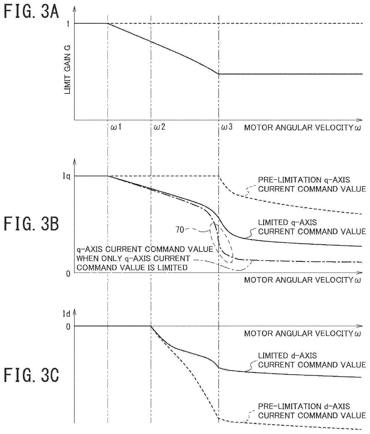
[0048]With reference to FIGS. 3A, 3B, and 3C, an action of the motor control device of the embodiment will be described. FIG. 3A broadly illustrates a relationship between the limit gain G and the motor angular velocity ω. FIG. 3B broadly illustrates relationships between the q-axis current command value Iq before limitation and the motor angular velocity ω and between the limited q-axis current command value Iq* and the motor angular velocity ω. FIG. 3C broadly illustrates relationships between the d-axis current command value Id before limitation and the motor angular velocity ω and between the limited q-axis current command value Id* and the motor angular velocity ω.
[0049]The dashed line, the solid line, and the alternate long and short dash line in FIG. 3B illustrate the q-axis current command value Iq before limitation by the limit gain G, the limited q-axis current command value Iq*, and a q-axis current command value when only the q-axis current command va...
second embodiment
[0067]Next, a second embodiment will be described. In FIG. 5, an example of a functional configuration of a control unit 30 of the second embodiment is illustrated.
[0068]A gain computation unit 51 of the control unit 30 of the second embodiment separately sets, as limit gains G, a q-axis limit gain Gq for limiting a q-axis current command value and a d-axis limit gain Gd for limiting a d-axis current command value. This configuration enables q-axis current and d-axis current to be prioritized over each other.
[0069]The other constituent components of the second embodiment are the same as the constituent components of the first embodiment, which was described with reference to FIG. 2.
[0070]The equation (2) above can be transformed into the equation (4) below by multiplying the q-axis current command value and the d-axis current command value by the q-axis limit gain Gq and the d-axis limit gain Gd, respectively.
[Math 4]
VR·IbatMAX=Kt·Gq ·Iq·ω+R 3 / 2·(Gd2Id2+Gq2Iq2)+Ploss (4)
[0071]Next...
PUM
 Abstract
Description
Claims
Application Information
 - R&D
- Intellectual Property
- Life Sciences
- Materials
- Tech Scout
- Unparalleled Data Quality
- Higher Quality Content
- 60% Fewer Hallucinations
Browse by: Latest US Patents, China's latest patents, Technical Efficacy Thesaurus, Application Domain, Technology Topic, Popular Technical Reports.
© 2025 PatSnap. All rights reserved.Legal|Privacy policy|Modern Slavery Act Transparency Statement|Sitemap|About US| Contact US: help@patsnap.com