
Power electronic circuit fault diagnosis method based on optimizing deep belief network

a deep belief network and power electronic circuit technology, applied in the field of power electronic circuit fault diagnosis, can solve the problems of large blindness in selecting initial connection weight and threshold, loss of effective fault information in the signal processing process, and inability to effectively distinguish fault types selected after transformation, etc., to improve the accuracy of power electronic circuit fault identification and remove redundancy and interference features

Active Publication Date: 2020-09-10
WUHAN UNIV
View PDF0 Cites 47 Cited by
  • Summary
  • Abstract
  • Description
  • Claims
  • Application Information

AI Technical Summary

Benefits of technology

The present patent aims to provide a more accurate and efficient method for identifying faults in power electronic circuits using a deep learning algorithm. The method involves extracting fault feature vectors, selecting important features, and optimizing the deep learning algorithm to improve fault diagnosis accuracy. The technical effects include improved accuracy in identifying power electronic circuit faults and avoiding the shortcomings of neural network over-learning and local minimum.

Problems solved by technology

The common signal identification methods include Fourier transform, Park transform and wavelet transform, but these methods may lead to loss of effective fault information in the signal processing process.
When there are multiple fault types, the fault feature selected after the transformation cannot effectively distinguish different fault types.
The knowledge fusion fault diagnosis method, such as artificial neural network method identification method is likely to fall into the locally optimal solution during training, and it has great blindness in selecting the initial connection weights and thresholds.
It is difficult to adjust parameters and select a fault feature vector.

Method used


Image

  • Power electronic circuit fault diagnosis method based on optimizing deep belief network
  • Power electronic circuit fault diagnosis method based on optimizing deep belief network
  • Power electronic circuit fault diagnosis method based on optimizing deep belief network

Examples


Embodiment Construction

[0051]The present disclosure will be further described below with reference to specific embodiments and the accompanying drawings.

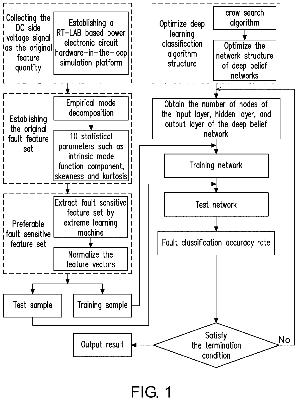
[0052]In the embodiment of the present disclosure, a five-level inverter is taken as an example, and a five-level inverter fault diagnosis method based on an optimized DBN, with reference to FIG. 1, includes the following steps.

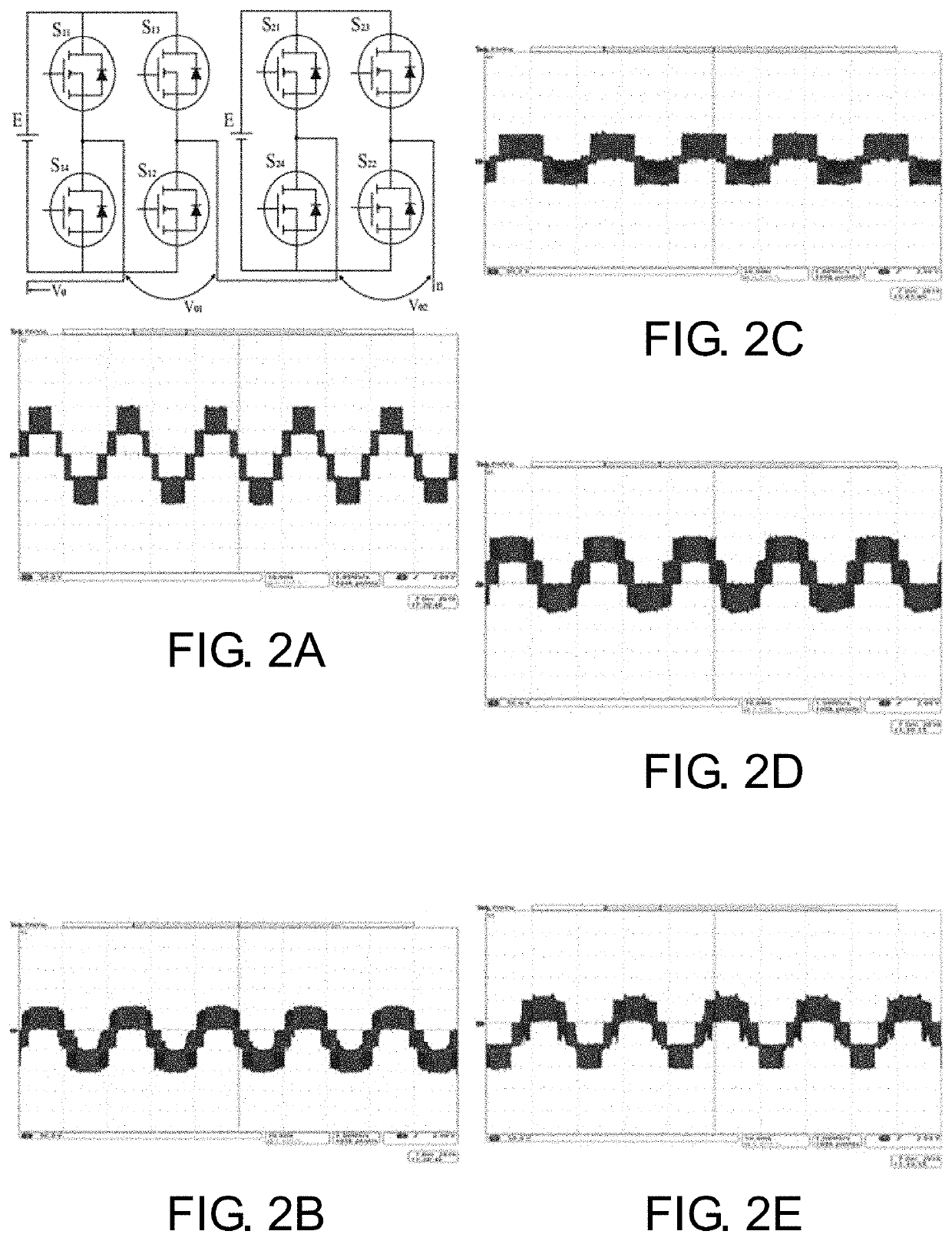
[0053](1) In order to verify the designed fault diagnosis method, non-real-time offline simulation is a common method, but a major shortcoming of this method is that there are many uncertain factors between offline simulation and actual prototype process. To make the fault diagnosis algorithm more practical, the fault experiment is carried out on the actual prototype using the RT-LAB hardware-in-the-loop simulator. The RT-LAB hardware-in-the-loop simulator is an industrial-level system real-time simulator introduced by Opal-RT Technologies of Canada. The dynamic system mathematical model established through MATLAB / Simulink can be d...


PUM


Abstract

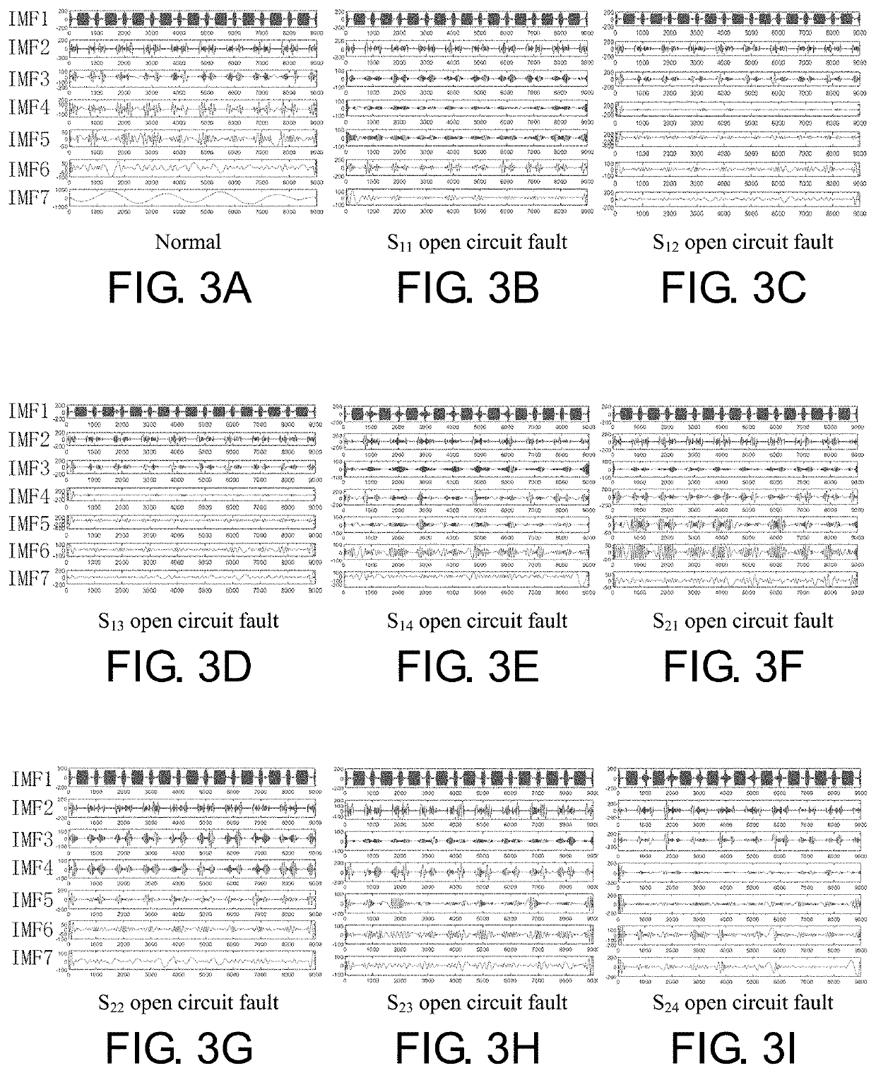
A fault diagnosis method for power electronic circuits based on optimizing a deep belief network, including steps. (1) Use RT-LAB hardware-in-the-loop simulator to set up fault experiments and collect DC-link output voltage signals in different fault types. (2) Use empirical mode decomposition to extract the intrinsic function components of the output voltage signal and its envelope spectrum and calculate various statistical features to construct the original fault feature data set. (3) Based on the feature selection method of extreme learning machine, remove the redundancy and interference features, as fault sensitive feature data set. (4) Divide the fault sensitive feature set into training samples and test samples, and primitively determine the structure of the deep belief network. (5) Use the crow search algorithm to optimize the deep belief network. (6) Obtain the fault diagnosis result.

Description

CROSS-REFERENCE TO RELATED APPLICATION[0001]This application claims the priority benefit of China application serial no. 201910169327.4, filed on Mar. 6, 2019. The entirety of the above-mentioned patent application is hereby incorporated by reference herein and made a part of this specification.BACKGROUNDTechnical Field[0002]The disclosure belongs to the field of power electronic circuit fault diagnosis, and particularly relates to a power electronic circuit fault diagnosis method based on optimized deep belief network.Description of Related Art[0003]The reliability of power electronic converter system is of paramount importance in energy, transportation, communications, industrial manufacturing, aerospace, environmental protection and defense military applications.[0004]The fault diagnosis of power electronic converter system is mainly for monitoring and diagnosis of power electronic devices in its main circuit. Currently, power electronic fault diagnosis methods are mainly divided...

Claims


Application Information

Patent Timeline
IPC IPC(8): G06K9/62G06N3/08G06N3/04G06F17/11
CPCG06F17/11G06K9/6259G06N3/04G06K9/6257G06N3/08G06N3/084G01R31/2846G06N5/01G06N3/047G06N3/044G06V10/7747G06V10/7753G06F18/2148G06F18/2155
Inventor HE, YIGANGDU, BOLUNZHANG, YARUDUAN, JIAJUNHE, LIULULIU, KAIPEI
Owner WUHAN UNIV
Learn More