Eureka AIR delivers breakthrough ideas for toughest innovation challenges, trusted by R&D personnel around the world.

Systems and methods for processing thin glass ribbons

Pending Publication Date: 2020-09-17
CORNING INC
View PDF12 Cites 0 Cited by
  • Summary
  • Abstract
  • Description
  • Claims
  • Application Information

AI Technical Summary

Benefits of technology

This patent relates to a method and system for processing glass ribbon. The technical effect of this patent is to provide a method and system that can support and move glass ribbon smoothly through a manufacturing process without causing any surface damage or scratches, and without causing any roll-off of the glass ribbon during processing. This is achieved by using a conveying apparatus with two support devices that create a non-rolling, line-type interface with the glass ribbon, and that are spaced apart along the travel path of the glass ribbon. The first support device is located upstream of the pulling device and the second support device is between the first and second support devices. The first and second support devices each establish a line-type interface with the glass ribbon, and can be gas bearing or sliding interfaces. The system also includes a glass ribbon forming apparatus for delivering the glass ribbon to the upstream side of the conveying apparatus.

Problems solved by technology

As the thickness of the glass ribbons from which the glass sheets are formed becomes thinner, they are also more susceptible to warp (or flatness deviations) and other concerns (such as surface damage that may be imparted during the process steps to provide a thinner glass ribbon).
Rollers inherently may not have perfect alignment with the glass ribbon travel direction, and may not have perfectly matched linear velocities.
The resulting effects are differential steering and pulling that can induce stresses that may cause deformation.
In addition to possibly generating some stretching at low viscosities, tensile stresses may also cause local slippage and potentially scratches.
However, with available air bearing conveyor devices, an intrinsic limitation exists at the edges of the air bearing device where the air bearing effect diminishes, resulting in direct contact with a support of the air bearing conveyor device.
For some end use applications, the linear contact applied by the nip rolls alone cannot achieve a desired level of flatness.

Method used


Image

  • Systems and methods for processing thin glass ribbons
  • Systems and methods for processing thin glass ribbons
  • Systems and methods for processing thin glass ribbons

Examples


Embodiment Construction

lass="d_n">[0024]Reference will now be made in detail to various embodiments of systems and methods for processing a glass ribbon, and in particular for removing warp from, or improving flatness in, a glass ribbon, for example a continuous glass ribbon. Whenever possible, the same reference numerals will be used throughout the drawings to refer to the same or like parts.

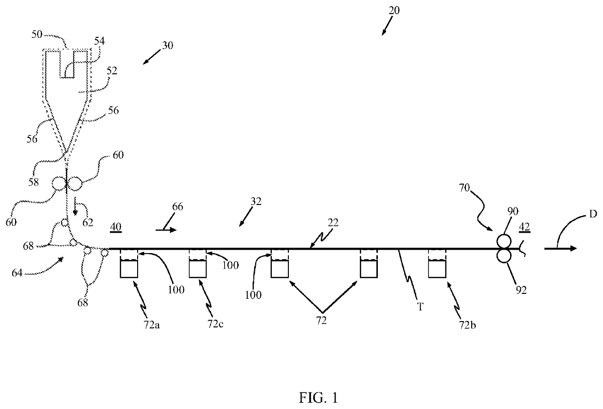
[0025]Some aspects of the present disclosure provide glass ribbon handling systems and methods in which a continuously conveyed or traveling glass ribbon is subjected to a cooling environment and is supported in such a way that desired flatness is minimally affected, if at all. With this in mind, one embodiment of a system 20 in accordance with principles of the present disclosure and useful in forming and processing a glass ribbon 22 is schematically shown in FIG. 1. Although the system 20 is described herein as being used to process a glass ribbon, it should be understood that the systems and methods of the present...


PUM

PropertyMeasurementUnit
Viscosityaaaaaaaaaa
Speedaaaaaaaaaa
Distanceaaaaaaaaaa

Abstract

Systems, apparatuses and methods for processing a glass ribbon (22). A glass ribbon is supplied to an upstream side of a conveying apparatus (32). A pulling force is applied on the glass ribbon (22) at a downstream side of the conveying apparatus (32). The glass ribbon (22) is supported at first and second support devices along a travel path of the conveying apparatus (32). Each of the first and second support devices (72) establishes a non-rolling, line-type interface with the glass ribbon (22). Further, the first support device (72a) is spaced from the second support device (72c) along the travel path. In some embodiments, the line-type interface comprises a sliding interface or a gas bearing interface.

Description

CROSS-REFERENCE TO RELATED APPLICATIONS[0001]This application claims the benefit of priority under 35 U.S.C. § 119 of U.S. Provisional Application Ser. No. 62 / 579,543 filed Oct. 31, 2017 and U.S. Provisional Application Ser. No. 62 / 618,259 filed Jan. 17, 2018, the content of each are relied upon and incorporated herein by reference in their entirety.BACKGROUNDField[0002]The present disclosure generally relates to systems and methods for processing a glass ribbon. More particularly, it relates to systems and methods for handling a glass ribbon as part of the manufacture of thin glass sheets from a moving glass ribbon.Technical Background[0003]Production of glass sheets typically involves producing a glass ribbon from a molten glass material, and then cutting or separating individual glass sheets from the glass ribbon. Various techniques are known for producing the glass ribbon. For example, with a down-draw process (e.g., fusion draw process), the ribbon is drawn downward, typically ...

Claims


Application Information

Patent Timeline
IPC IPC(8): C03B17/06B65H23/24B65H20/00C03B35/24
CPCC03B35/16C03B17/064C03B17/068B65H20/00C03B35/246B65H23/24B65H2801/61C03B35/166C03B35/181C03B23/023B65H23/04B65H2301/51212
Inventor BISSON, ANTOINE GASTON DENIS
Owner CORNING INC
Why Eureka
Eureka Blog
Learn More