Torque limiter device

Pending Publication Date: 2020-09-17
EXEDY
View PDF10 Cites 1 Cited by
  • Summary
  • Abstract
  • Description
  • Claims
  • Application Information

AI Technical Summary

Benefits of technology

[0019]Overall, according to the present invention described above, it is possible to achieve compactness in radial

Problems solved by technology

Incidentally, this type of vehicle has a large inertia amount on the output side.
Because of this, chances are that in engine starting and so forth, a torque fluctuates with a large amp

Method used


Image

  • Torque limiter device
  • Torque limiter device
  • Torque limiter device

Examples


Example

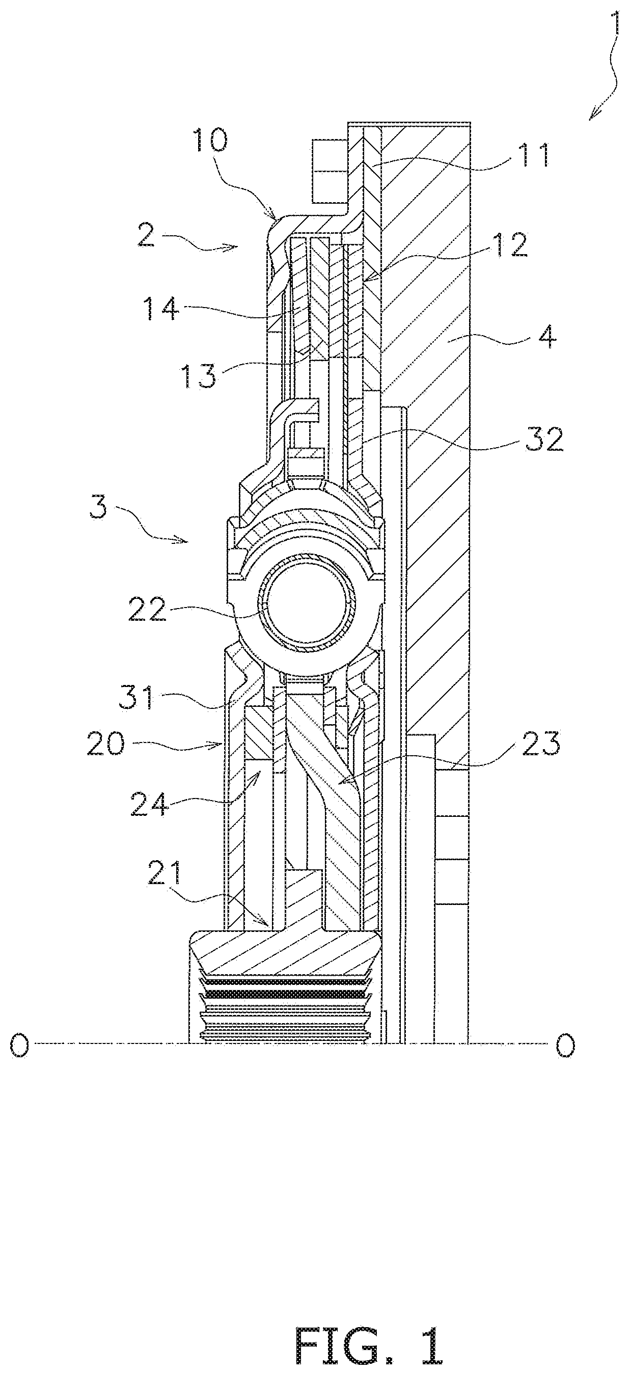
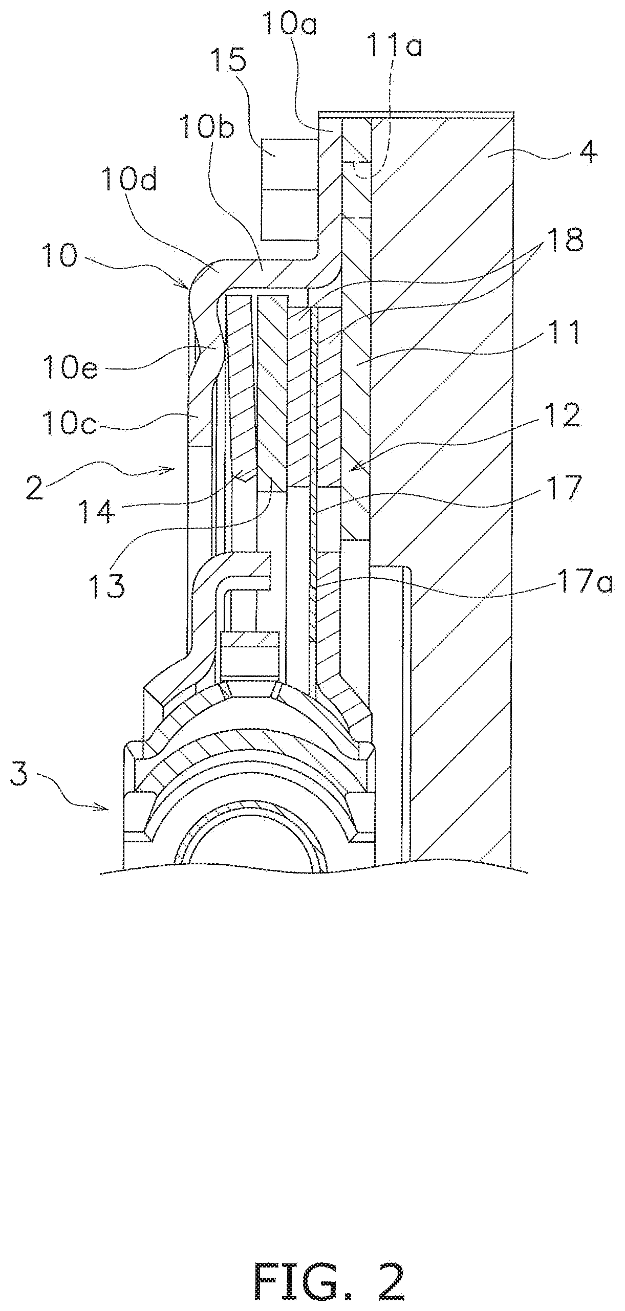
[0027]FIG. 1 is a cross-sectional view of a power transmission device 1 including a damper device according to a preferred embodiment of the present invention. FIG. 2 is a front view of the power transmission device 1 that part of members is detached therefrom. The power transmission device 1 is installed in, for instance, a hybrid vehicle. The power transmission device 1 includes a torque limiter device 2 and a damper device 3 that power generated in an engine is inputted thereto through the torque limiter device 2. The engine is disposed on the right side in FIG. 1, whereas an electric motor, a transmission and so forth are disposed on the left side in FIG. 1. In FIG. 1, line O-O indicates a rotational axis.

[Torque Limiter Device 2]

[0028]The torque limiter device 2 is coupled to a flywheel 4 to which the power generated in the engine is inputted. Additionally, when an excessive torque is inputted from an output side, for instance, the torque limiter device 2 limits the magnitude o...


PUM


Abstract

A torque limiter device for limiting a torque transmitted between a power source-side member and an output-side member is disclosed. The torque limiter device includes a cover, a friction disc and an urging member. The cover includes a coupling portion, a tubular portion and a support portion. The coupling portion is coupled to the power source-side member. The tubular portion axially extends from the coupling portion. The support portion extends from the tubular portion to an inner peripheral side. The friction disc is accommodated in an inner peripheral space of the tubular portion of the cover, and is pressed toward the power source-side member. The urging member is supported by the support portion of the cover, and urges the friction disc toward the power source-side member.

Description

CROSS-REFERENCE TO RELATED APPLICATIONS[0001]This application claims priority to Japanese Patent Application No. 2019-049048, filed Mar. 15, 2019. The contents of that application are incorporated by reference herein in their entirety.TECHNICAL FIELD[0002]The present invention relates to a torque limiter.BACKGROUND ART[0003]A hybrid vehicle, in which an engine and an electric motor are used in combination, is provided with a damper device between the engine and a drive unit disposed on an output side in order to inhibit fluctuations in rotation of the engine. Incidentally, this type of vehicle has a large inertia amount on the output side. Because of this, chances are that in engine starting and so forth, a torque fluctuates with a large amplitude and an excessive torque is transmitted to the engine side.[0004]In view of this, there has been proposed a damper device including a torque limiter as described in Japan Laid-open Patent Application Publication No. 2012-210937. The torque ...

Claims


Application Information

Patent Timeline
IPC IPC(8): F16D7/02F16F15/121
CPCF16F15/1219F16F15/1213F16D7/025F16D43/215F16F15/13469F16F15/1397B60K6/40F16F15/1292F16F15/1297
Inventor TOMITA, YUSUKEOKAMACHI, YUSUKE
Owner EXEDY
Why Eureka
Try Eureka