Soft robotic gripper with hybrid structure and grasping reliability

a hybrid structure and robotic gripper technology, applied in the field of soft robotic grippers with hybrid structure and grasping reliability, can solve the problems of lack of structural rigidity, remarkable drawbacks, design problems, etc., and achieve the effects of maintaining inherent compliance, small material deformation resistance, and robust structur

Active Publication Date: 2020-09-24
THE UNIVERSITY OF HONG KONG
View PDF0 Cites 3 Cited by
  • Summary
  • Abstract
  • Description
  • Claims
  • Application Information

AI Technical Summary

Benefits of technology

[0006]Embodiments of the subject invention provide a distinctive soft robotic gripper by combining a hybrid actuation mechanism by combining linear soft actuators with rigid joints, and independent joint control. A soft gripper, as shown in FIG. 1, can provide robust structure rigidity while maintaining inherent compliance at the same time. The actuation mechanism with a small material deformation resistance can realize a high output force to input pressure ratio. Programmable versatile grasping modes can be selected f

Problems solved by technology

However, the inherent compliance of soft end effector also brings remarkable drawbacks, especially as lack of structural rigidity.
However, the tradeoff between structure rigidity and compliance creates a design problem.
This is appropriate for power and envelope grasping, but is not reliable for parallel grasping.
Passive deformation of the finger is no

Method used


Image

  • Soft robotic gripper with hybrid structure and grasping reliability
  • Soft robotic gripper with hybrid structure and grasping reliability
  • Soft robotic gripper with hybrid structure and grasping reliability

Examples


example 1

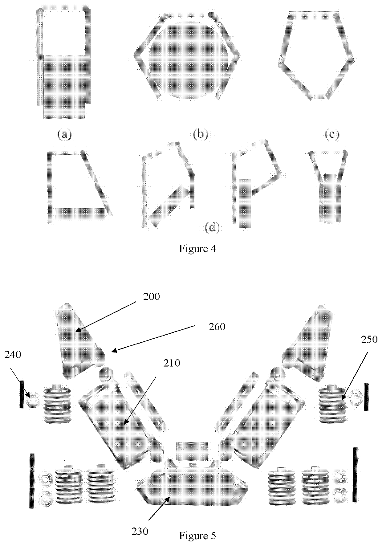
[0037]To fabricate a two-finger soft gripper, the design parameters as shown in Table II were chosen. The CAD assembly of the soft gripper comprising two fingers 260 is presented in FIG. 5. A smaller ratio of bellows 250 at the proximal joint to the distal joint, leads to better compliance of the gripper. Therefore, two pneumatic bellows 250 were set at the proximal joint between the base 230 and the proximal phalange 210. One bellows 250 was set at the distal joint between the proximal phalange 210 and the distal phalange 200, as seen in FIG. 5. Pins and bearings 240 were used for assembly. This configuration helps to provide different joint stiffness when applying the same pressure, which provides better compliance with the grasping target. To enhance contact friction, contact areas 220 of the gripper were casted with a layer of silicone wave surface skin using Dragon skin 10. The prototype gripper was mainly fabricated by material deposition method, with a commercially available ...

example 2

[0039]The relationship between the joint bending angle and supplied pressure under no payload was measured. The results, as shown in FIG. 7A, demonstrate that the soft gripper can arrive at a large working range with a low supplied pressure within 40 kPa.

example 3

[0040]The high energy transfer ratio of the mechanism was measured. The results, as shown in FIG. 7B demonstrates that the soft gripper can achieve 30N output force within an applied 1 Bar of input pressure, which is close to the theoretical maximum output force with minimum energy loss.


PUM


Abstract

A robotic end effector and method for use thereof are provided. The robotic end effector can include a rigid base structure (230), a plurality of rigid proximal phalanges (210) connected to the rigid base structure (230), a plurality of rigid distal phalanges (200) connected to the proximal phalanges (210) respectively, and a plurality of bellows (250), wherein one end of a proximal phalange (210) is connected to one end of the base structure (230) by a bellows (250), wherein one end of a distal phalange (200) is connected to a proximal phalange (210) by a bellows (250), and wherein a portion of the base structure (230), each proximal phalange (210), and each distal phalange (200) are covered in silicone rubber. It can achieve a high output force to input pressure ratio, and cost efficiently.

Description

BACKGROUND[0001]A robotic end effector is a crucial connection for robots interacting with the environment and human beings. With the development of robotic systems, robots have been more widely applied in daily life and routines. From experimental and industrial fields to versatile and human centered environments, the primary design concerns of robotic end effectors have shifted from industrial concerns (accuracy, strength, speed, etc.) to human centered criteria, such as weight, safety, adaptability, task-worthiness, and affordability.[0002]Following the shift of design requirements, avenues such as underactuation and variable stiffness mechanisms have been utilized for compliant grasping. In recent years, another approach for human centered end effector design, has involved the development of a soft robot. The soft robot provides inherent compliance and adaptability for safe human robot interaction as service robots, rehabilitation robots, personal robots, etc. Furthermore, with ...

Claims


Application Information

Patent Timeline
IPC IPC(8): B25J15/00B25J9/14
CPCB25J15/0023B25J9/142B25J15/0028B25J15/10B25J15/0009
Inventor WANG, ZHENGZHOU, JIANSHU
Owner THE UNIVERSITY OF HONG KONG
Why Eureka
Try Eureka