
Polarizing plate and liquid crystal display device

a liquid crystal display device and polarizing plate technology, applied in the field of polarizing plate and liquid crystal display device, can solve the problems of harmful blue light damage to eyes, serious threat to people's eye health, and exposure to blue light, so as to reduce the influence of the overall thickness of the polarizing plate, reduce the proportion of short wavelength band blue light, and reduce the effect of blue light damag

Active Publication Date: 2020-09-24
WUHAN CHINA STAR OPTOELECTRONICS TECH CO LTD
View PDF0 Cites 2 Cited by
  • Summary
  • Abstract
  • Description
  • Claims
  • Application Information

AI Technical Summary

Benefits of technology

The present disclosure provides a polarizing plate and a liquid crystal display device that reduces harmful blue light that can cause damage to the eyes, especially children and adolescents. The solution aims to protect the eyes while ensuring the display does not distort. Compared to other solutions, the polarizing plate effectively filters out harmful blue light and does not impact other wavelength bands. It also avoids adding extra film to the structure which helps reduce costs and improve usability. This invention addresses the issue of short wavelength band blue light in liquid crystal display devices and ensures a safer viewing experience for users.

Problems solved by technology

In particular, short-wavelength band blue light having wavelength less than 455 nm causes an increasing amount of toxin in the macular of eyes, which seriously threatens people's eye health.
Blue light can be seen everywhere in daily life, but LED liquid crystal display devices are a main source of harmful blue light that people are exposed to.
Those circumstances together with splash screens and other factors cause harmful blue light to damage the eyes.
Long-term accumulation causes eye fatigue, dryness, and decreased vision.
However, this method is costly and needs to be purchased by consumers.
At the same time, the method will make picture effect worse, that is, pictures look yellowish.
In addition, the method will reduce display brightness.
At the same time, there is still a problem that the picture looks yellowish.
Therefore, for common existing short wavelength band blue light with a wavelength less than 455 nm of the current liquid crystal display devices, it causes irreversible damage to eyes of users, especially to the eyes of children and adolescents.
The method of eye protection from short wavelength band blue light currently generally has a problem of distortion of picture colors.

Method used


Image

  • Polarizing plate and liquid crystal display device
  • Polarizing plate and liquid crystal display device
  • Polarizing plate and liquid crystal display device

Examples


Embodiment Construction

[0024]The following description of the embodiments is provided by reference to the following drawings and illustrates the specific embodiments of the present disclosure. Directional terms mentioned in the present disclosure, such as “up,”“down,”“top,”“bottom,”“forward,”“backward,”“left,”“right,”“inside,”“outside,”“side,”“peripheral,”“central,”“horizontal,”“peripheral,”“vertical,”“longitudinal,”“axial,”“radial,”“uppermost” or “lowermost,” etc., are merely indicated the direction of the drawings. Therefore, the directional terms are used for illustrating and understanding of the application rather than limiting thereof.

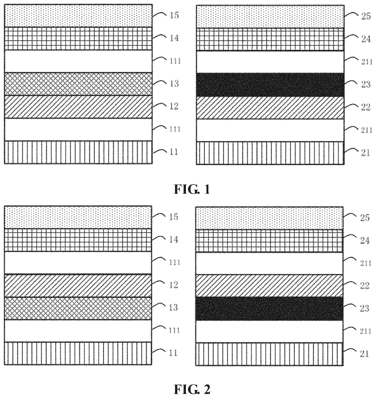
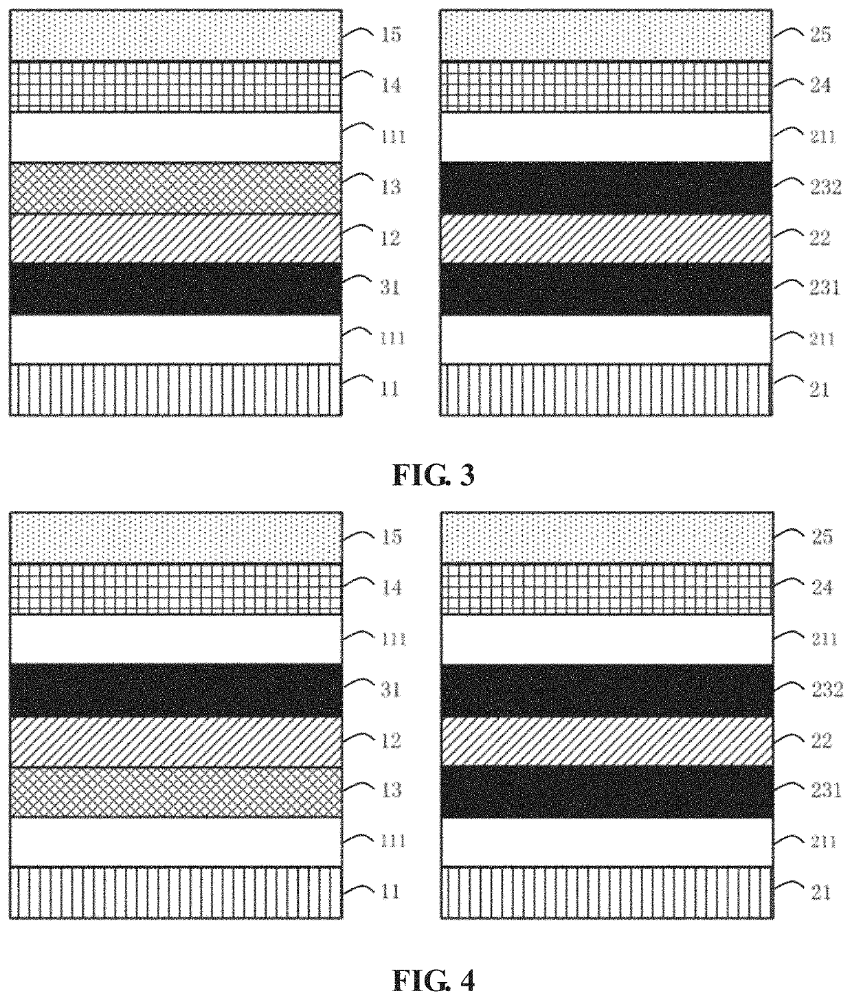
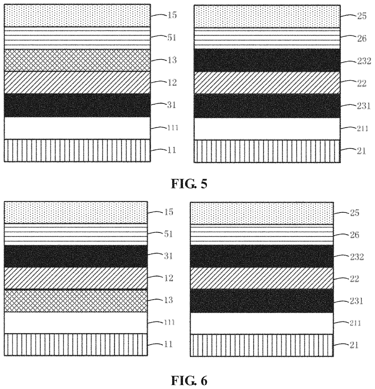
[0025]One embodiment of the present invention provides a polarizing plate. The polarizing plate includes a polarizing layer, a short wavelength band blue light film, a release film, and a protective film. The short wavelength band blue light film is disposed on an upper side or a lower side of the polarizing layer. The release film is disposed on a lower side of the pol...


PUM

PropertyMeasurementUnit
wavelengthaaaaaaaaaa
wavelength bandaaaaaaaaaa

Abstract

A polarizing plate and a liquid crystal display device are provided. The polarizing plate includes a polarizing layer, a short wavelength band blue light film, a supporting layer, a release film, and a protective film. The short wavelength band blue light film is disposed on an upper side or a lower side of the polarizing layer. The supporting layer is disposed on a side of the polarizing layer opposite another side of the pluralizing layer facing the short wavelength band blue light film. The release film is disposed on a lower side of the polarizing layer. The release film is connected to the polarizing layer or the short wavelength band blue light film through an adhesive layer.

Description

FIELD OF INVENTION[0001]The present disclosure relates to liquid crystal display technologies, and more particularly, to a polarizing plate, and a liquid crystal display device.BACKGROUND OF INVENTION[0002]With rapid development of electronic technologies and display technologies, liquid crystal displays (LCDs) have been widely used in, such as LCD TVs, smart phones, computers, tablets, and other modern information equipment. Most liquid crystal display devices on the market are backlight type liquid crystal display devices, which include a liquid crystal display panel and a backlight module (BLU).[0003]The liquid crystal display panel is usually composed of a color filter (CF) substrate, a thin film transistor (TFT) array substrate, and a liquid crystal layer (LCL) disposed between these two substrates. A polarizing plate is attached to a side of the CF substrate opposite another side of the CF substrate facing the liquid crystal layer. Another polarizing plate is attached to a sid...

Claims


Application Information

Patent Timeline
Patent Type & Authority Applications(United States)
IPC IPC(8): G02F1/1335
CPCG02B5/3025G02F1/133509G02F1/133528G02F2202/28G02B1/10G02B1/14G02B5/3033G02F2201/50
Inventor MA, GUIZHILI, YONGKAI
Owner WUHAN CHINA STAR OPTOELECTRONICS TECH CO LTD
Learn More