Coil segment cutting method and coil segment cutting apparatus

a cutting method and cutting apparatus technology, applied in electrical apparatus, dynamo-electric machines, manufacturing dynamo-electric machines, etc., can solve problems such as accumulating non-uniformity, blowholes or the like, and deteriorating mechanical characteristics or electrical characteristics, and achieve high-quality welding

Active Publication Date: 2020-09-24
ODAWARA ENG
View PDF0 Cites 4 Cited by
  • Summary
  • Abstract
  • Description
  • Claims
  • Application Information

AI Technical Summary

Benefits of technology

[0023]According to the present invention, end portions of coil segments can be cut into a uniform length to enable high quality welding.

Problems solved by technology

In this case, if the lengths of the peeled-off portions in the axial direction of the core are not uniform, blowholes or the like tends to occur at the time of welding.
This may cause deterioration of the mechanical characteristics or electrical characteristics over time in the rotary electric machine to be manufactured.
In such segment type coils, non-uniformity is accumulated in each process of cutting the straight wire to a predetermined length, bending them into the U-shape, inserting them into the slots, and twisting them.
Thus, lengths of the peeled-off portions are likely to be uneven after the twisting.
Although it has also been performed to cut manually using a cutting tool, the cutting accuracy is lower than mechanical processes in which a movable blade is moved by a drive mechanism.

Method used


Image

  • Coil segment cutting method and coil segment cutting apparatus
  • Coil segment cutting method and coil segment cutting apparatus
  • Coil segment cutting method and coil segment cutting apparatus

Examples


Embodiment Construction

[0045]Hereinafter an embodiment of the present invention will be described with reference to the drawings. First, a coil segment cutting method using a coil segment cutting apparatus according to the present embodiment will be described.

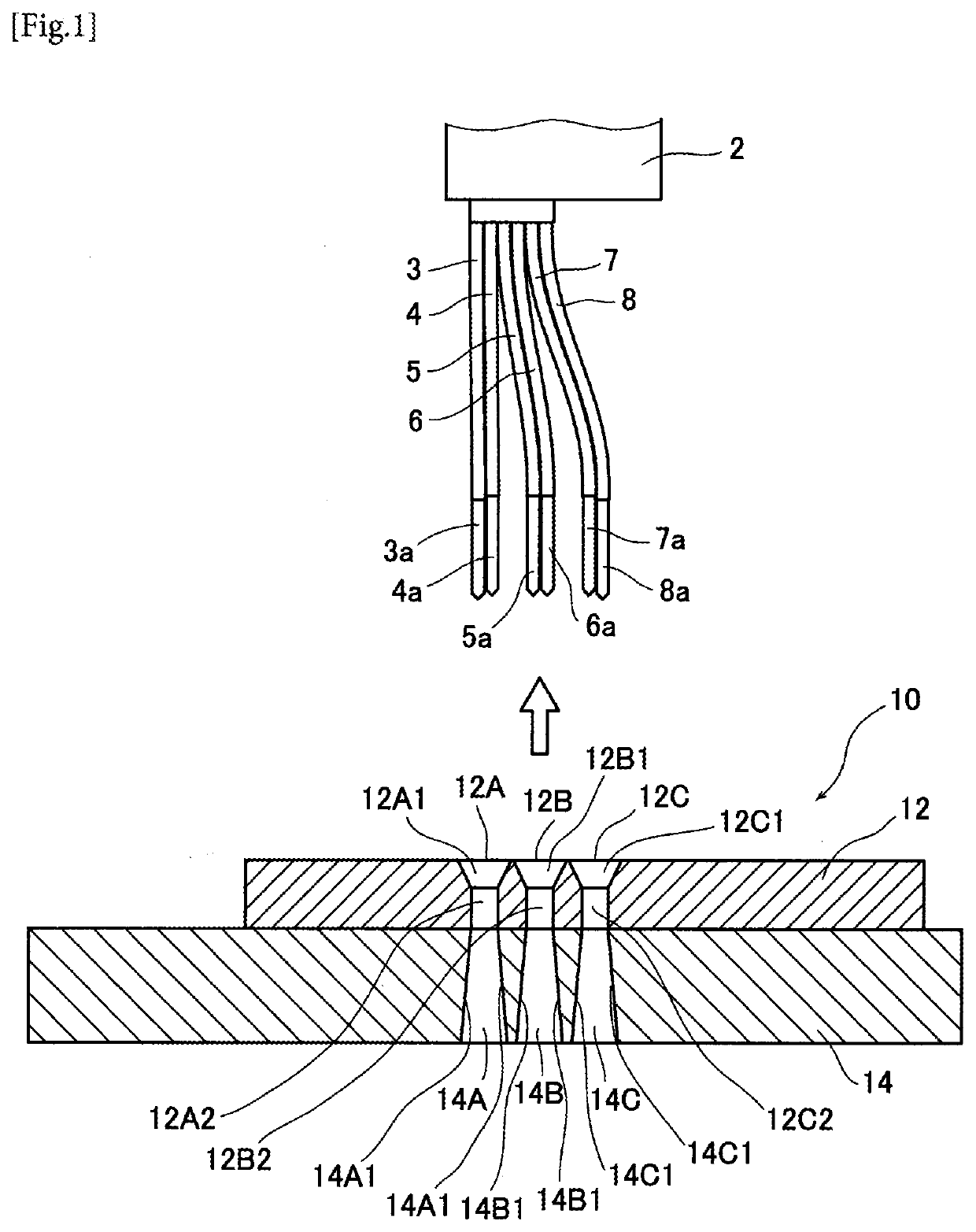
[0046]This cutting method is, as shown in FIG. 1, a method of cutting distal ends of respective segment end portions 3, 4, 5, 6, 7, and 8 which are respective end portions of a plurality of coil segments, protruding from an end face of a core 2, wherein the coil segments are respectively inserted into slots of the core 2 of a stator or rotor to form a plurality of layers (six layers here) in the radial direction of the core 2. The cut is performed for aligning positions (heights along the axial direction of the core) of apexes of peeled-off portions 3a, 4a, 5a, 6a, 7a, and 8a at the distal ends of the segmented end portions 3 to 8. Incidentally, only a portion of the core 2 in a cylindrical shape is shown in FIG. 1.

[0047]The peeled-off portion is a p...


PUM


Abstract

A cutting unit has a support member having insertion holes, and a movable member having through holes connected thereto. The respective left sides of upper surfaces of the square through holes are first movable blades, and the respective right sides thereof are second movable blades. Firstly, the movable member 14 is moved to the right by a predetermined amount to cut peeled-off portions of segment end portions only, and then the movable member is moved to the left by a predetermined amount to cut peeled-off portions of the segment end portions only. Distal ends of the coil segments can be cut into a uniform length to enable high quality welding, through this process.

Description

TECHNICAL FIELD[0001]The present invention relates to a coil segment cutting method and a coil segment cutting apparatus of cutting end portions (legs) of coil segments protruding from an end face of a core of a stator or rotor in an electrical rotating machine (rotary electric machine) such as a motor or a generator.BACKGROUND ART[0002]As a coil of a stator or rotor in an electrical rotating machine, so-called segment type coil is known, in which a plurality of coil segments (hereinafter, simply referred to also as segments), each formed by bending a straight wire rod of a predetermined length into a U-shape, are respectively inserted into a plurality of slots arranged along the circumferential direction of the stator or rotor, distal end portions in the insertion direction (segment end portions) of the segments protruding from the end face of the core are twisted, and the peeled-off portions at the ends thereof in which an insulative coating material is peeled off are electrically...

Claims


Application Information

Patent Timeline
Patent Type & Authority Applications(United States)
IPC IPC(8): H02K15/04
CPCH02K15/0421H02K15/0081H02K3/12
Inventor MIYAZAKI, YUJIMIYAWAKI, NOBURO
Owner ODAWARA ENG
Why Eureka
Try Eureka