Short-path evaporator

a short-path evaporator and evaporator technology, applied in the direction of evaporators with vertical tubes, vapor condensation, evaporation, etc., can solve the problems of requiring a considerable amount of working time and labor costs, and achieve the effect of simple structure and easy manufacture and assembly

Active Publication Date: 2020-10-01
BUBLIES JULIAN ALEXANDER
View PDF0 Cites 1 Cited by
  • Summary
  • Abstract
  • Description
  • Claims
  • Application Information

AI Technical Summary

Benefits of technology

[0006]It is one object of this invention to provide a short path evaporator of the type mentioned abov

Problems solved by technology

However, the problem with these short path evaporators is that, due to the tightness required for operation in a vacuum, they are often manufactured either as a welded stainless steel structure or in the form of a complex glass component, wherein at least the double-walled evaporator pipe is integrally manufactured together with the conn

Method used


Image

  • Short-path evaporator
  • Short-path evaporator
  • Short-path evaporator

Examples


Embodiment Construction

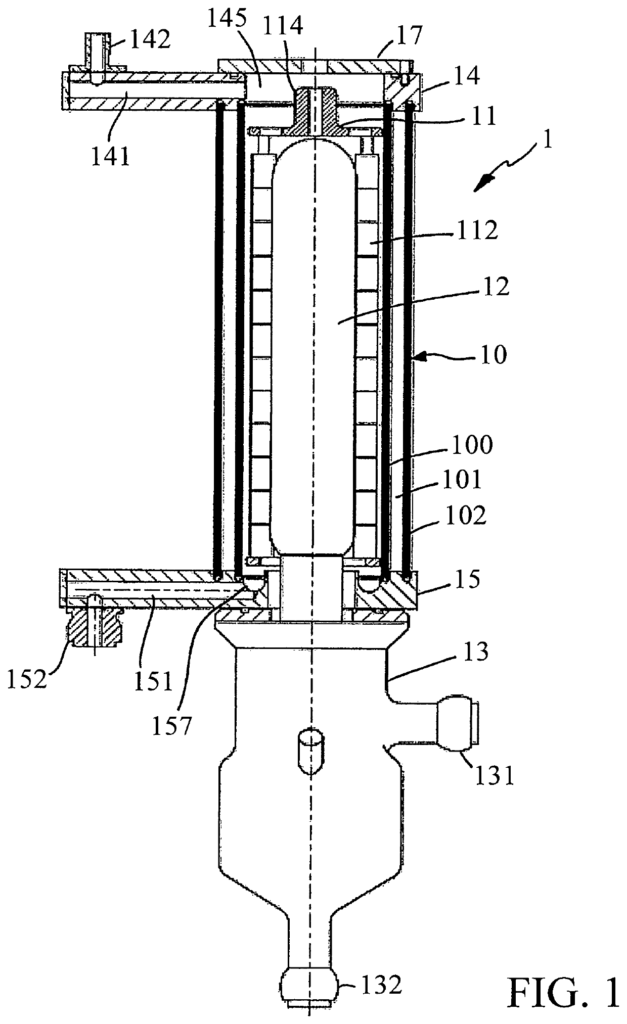
[0026]In FIG. 1, a short path evaporator 1, which can be used for the gentle distillation of organic products, is shown in a partial sectional view.

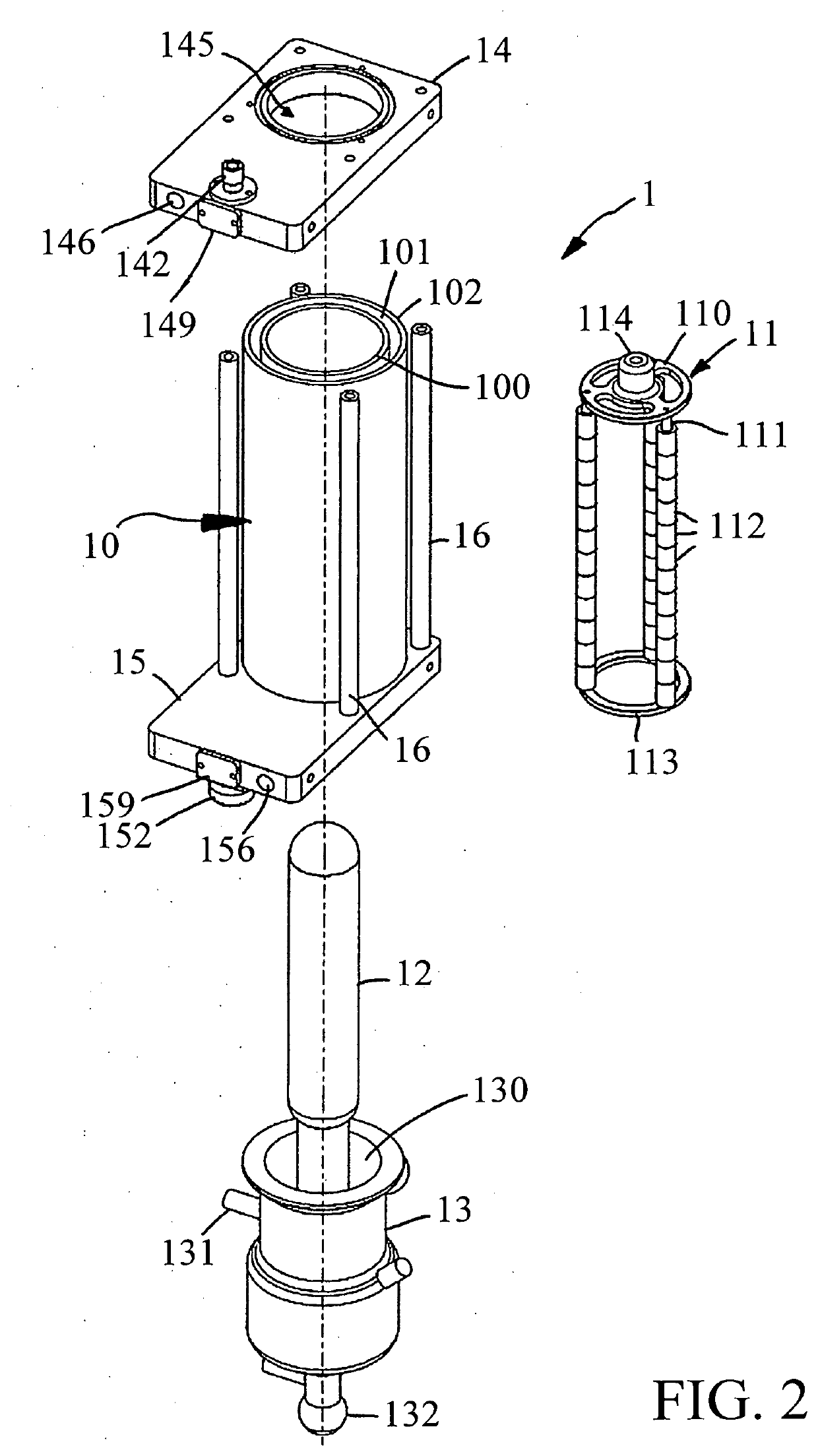
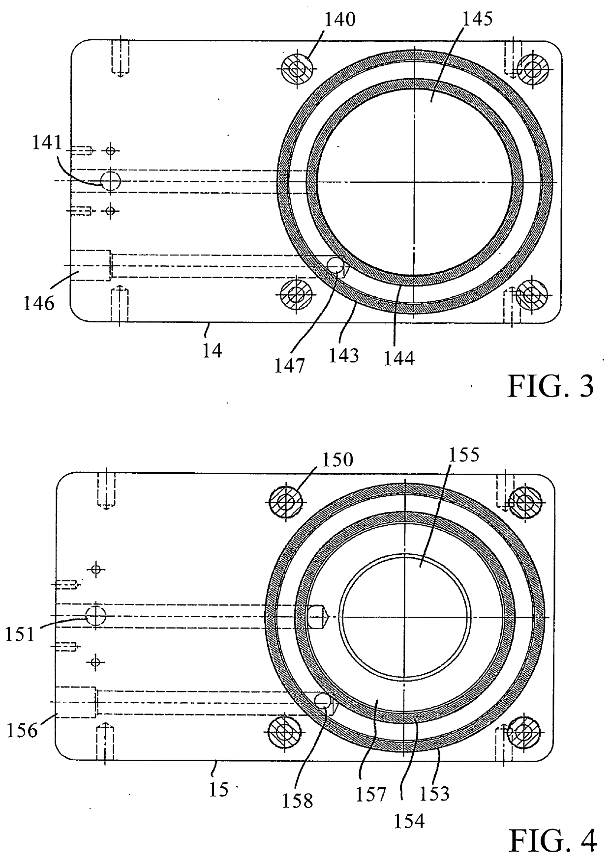
[0027]As is also apparent in other details from the FIGS. 2-4, the short path evaporator 1 comprises, as an essential component, a vertically oriented evaporator pipe 10, which can be heated in a manner described in more detail below, and a rotor system 11, which is disposed within the evaporator pipe 10 and which can be driven to rotate about the vertical axis with a rotary drive not shown, and with a condenser 12, which is centrally disposed within the evaporator pipe 10 and within the rotor system 11, and which can be cooled in a manner not shown in any detail.

[0028]Such a short path evaporator 1 is based on a supplied liquid product, which is to be distillated, being spread in a thin layer onto the inner wall of the heated evaporator pipe 10 by the rotor 11, which is driven to rotate, wherein the highly volatile constituents of the p...


PUM


Abstract

A short path evaporator including a heatable double-walled evaporator pipe having an inner interspace, with a rotatable rotor system disposed within the evaporator pipe and with a condenser disposed centrally in the evaporator pipe, and with an inlet for a product leading into the evaporator pipe, an outlet for a concentrate of the product leading out of the evaporator pipe, and an outlet for distillate accumulating at the condenser, and an inlet and an outlet for supplying and discharging heating medium to or from the interspace of the evaporator pipe, wherein the evaporator pipe is formed by an outer pipe and an inner pipe which, leaving the interspace, is disposed within the outer pipe, which are fixed at their ends in a sealing manner between two flange plates clamped together, wherein an inlet channel for the inlet of the product and an outlet channel for the outlet of the concentrate, which communicate with the interior of the inner pipe, are formed in the flange plates, as well as inlet and outlet channels for supplying and discharging the heating medium, which communicate with the interspace.

Description

CROSS REFERENCE TO RELATED APPLICATIONS[0001]This application claims the benefit of U.S. Provisional Patent Application Ser. No. 62 / 827,364, filed on 1 Apr. 2019. The co-pending Provisional Patent Application is hereby incorporated by reference herein in its entirety and is made a part hereof, including but not limited to those portions which specifically appear hereinafter.BACKGROUND OF THE INVENTIONField of the Invention[0002]This invention relates to a short path evaporator, including a heatable double-walled evaporator pipe, which has an inner interspace, with a rotatable rotor system disposed within the evaporator pipe and with a condenser disposed centrally in the evaporator pipe, and with an inlet for a product leading into the evaporator pipe, an outlet for a concentrate of the product leading out of the evaporator pipe, an outlet for distillate accumulating at the condenser, and an inlet and an outlet for supplying and discharging heating medium to or from the interspace of...

Claims


Application Information

Patent Timeline
IPC IPC(8): B01D1/08B01D1/00
CPCB01D1/223B01D1/0041B01D1/0064B01D1/08B01D5/006
Inventor BUBLIES, JULIAN ALEXANDER
Owner BUBLIES JULIAN ALEXANDER
Why Eureka
Try Eureka