Automated Extracorporeal Blood Treatment Apparatus

a treatment apparatus and extracorporeal technology, applied in the direction of suction devices, medical devices, other medical devices, etc., can solve the problems of air/blood interface, dialyzer manipulation, and higher risks of contamination of inside sterile content, so as to facilitate the treatment process, reduce labor and supply costs, and ensure home treatment.

Pending Publication Date: 2020-10-08
NEXTKIDNEY SA
View PDF7 Cites 2 Cited by
  • Summary
  • Abstract
  • Description
  • Claims
  • Application Information

AI Technical Summary

Benefits of technology

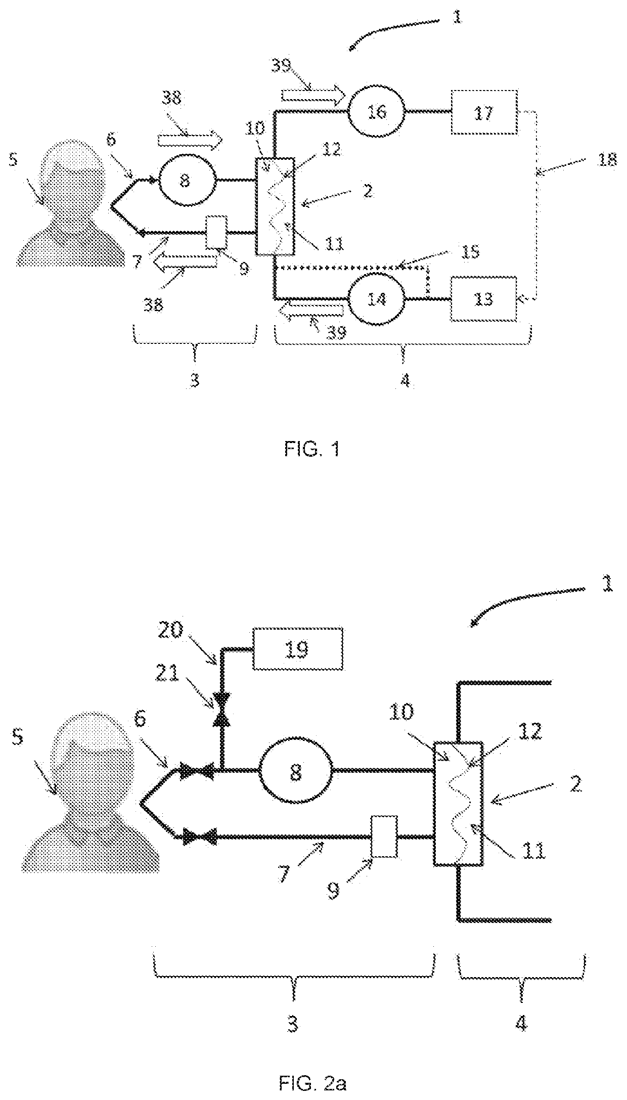
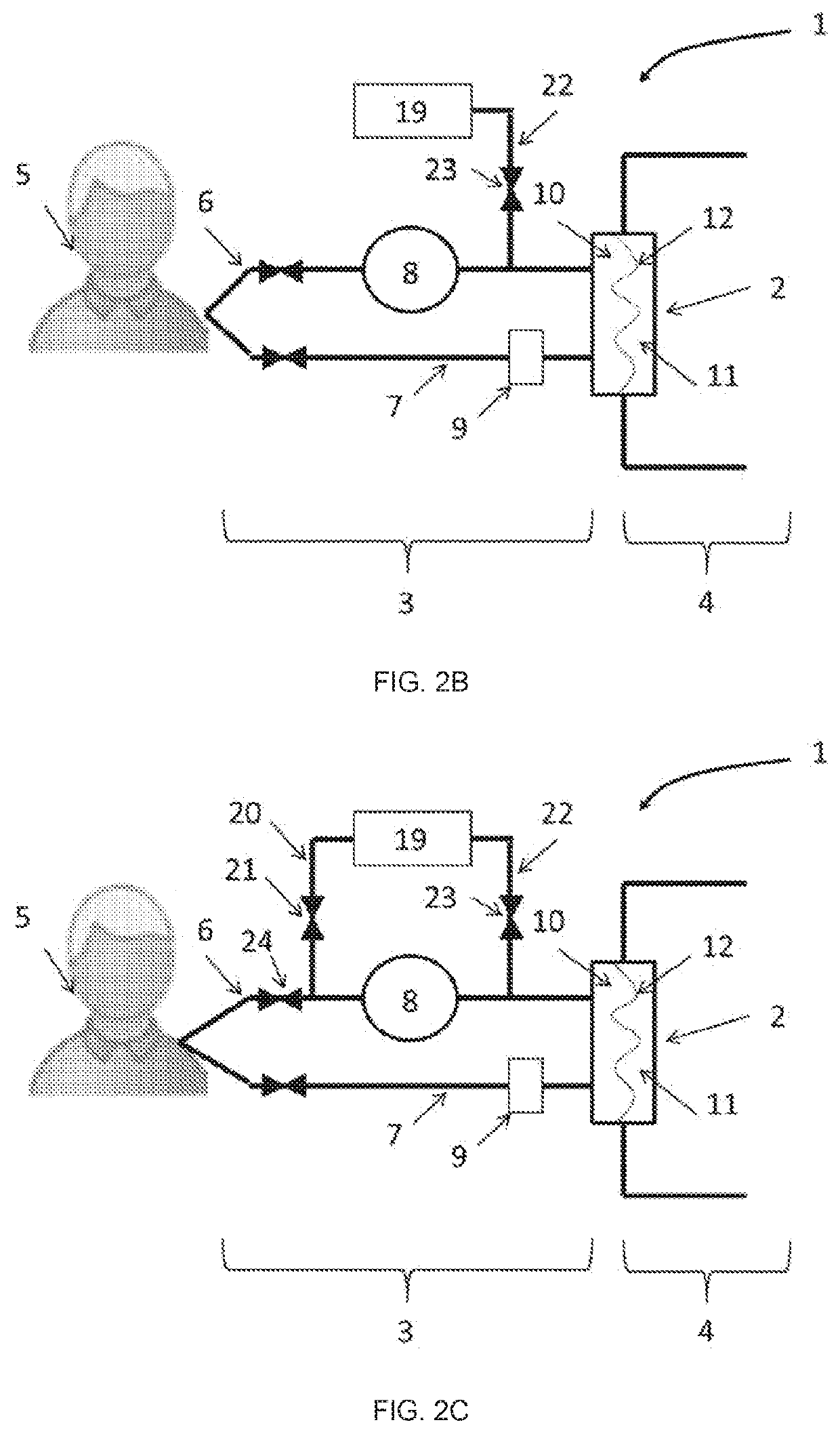
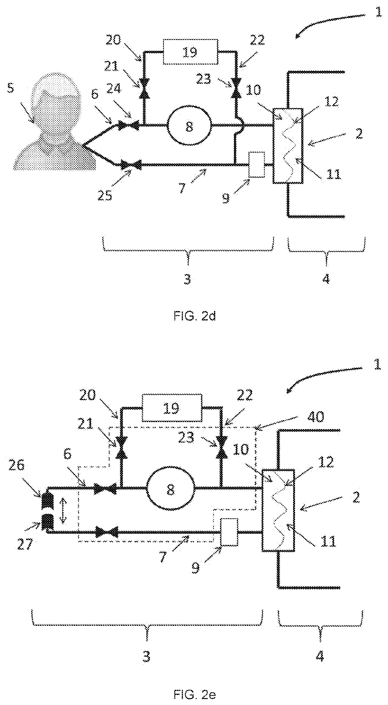
[0019]invention first aspect of the invention provides an extracorporeal dialysis apparatus which allows the automation of some operations in order to make possible a safe home treatment or to facilitate the treatment process for example the priming and/or the blood return process. Such an apparatus allow to automatically perform a series of processes from hemodialysis preparation to treatment completion

Problems solved by technology

Furthermore, the more connections done by the patient/healthcare professional, the higher are the risks of contamination of the inside sterile content.
And manipulation of the dialyzer represents a risk of less efficient priming if not well oriented during its specific priming phase.
If the dialyzer is oriented in the wrong

Method used


Image

  • Automated Extracorporeal Blood Treatment Apparatus
  • Automated Extracorporeal Blood Treatment Apparatus
  • Automated Extracorporeal Blood Treatment Apparatus

Examples


embodiment 700

[0388]The FIG. 37 shows another potential embodiment 700 having an apparatus 701, a display device 710, a door 704 allowing accessing to the cassette holder(s) and a heating compartment 705. In this embodiment, the loading system may move up and down the cassette holder with the door.

[0389]The FIG. 39 shows the system 700 in functional condition. The system further comprises a sorbent device 712, the tubes 713 of the fluid circuit and the weighing bag 714.

[0390]Loading System

[0391]Two distinct loading systems may be used for the apparatus (for example shown by the FIGS. 13 to 17). For both systems, the loading system 400 comprises at least one of a drive mechanism and a cassette holder 401 intended to removably receive a cassette. The cassette holder 401 is arranged into the housing of the apparatus. The aim of the loading system may be to enable the coupling between dedicated active elements 404 (also called components), 403, 402 of the apparatus and the cassette 106. Preferentiall...

first embodiment

[0407] the drive mechanism is adapted to move the cassette holder (also called movable holder of cassette) relatively to the apparatus (for example to at least one of the housing, to the opening, and the fixed support of components). The support 406 of the dedicated active elements 406 (also called fixed support of components) may be firmly secured into the apparatus and are not moved by the drive mechanism.

second embodiment

[0408] the drive mechanism is adapted to move one or more dedicated active elements (for example the support (also called movable support of components)) relatively to apparatus (for example to at least one of the housing, to the opening and the fixed holder of the cassette). The cassette holder (also called fixed holder of the cassette) may be firmly secured into the apparatus and are not moved by the drive mechanism.

[0409]According to another embodiment, the drive mechanism is adapted to move one or more dedicated active elements and the cassette holder relatively to apparatus. Thus, the drive mechanism is used to bring the dedicated active elements and the cassette holder closer or to move away.

[0410]In all cases, preferentially, the opening(s) of the housing does (do) not move with the drive mechanism. In other terms, the opening(s) of the housing may be fixed and / or may have a fixed perimeter. Thus, according to the first embodiment described above, the openings of the cassette...


PUM


Abstract

The present invention provides an extracorporeal dialysis apparatus which allows the automation of some operations in order to make possible a safe home treatment or to facilitate the treatment process for example the priming and/or the blood return process. Thus, the object is to automatically perform a series of processes from hemodialysis preparation to treatment completion safely, reliably and speedily, and to significantly reduce the labor and supply costs.

Description

FIELD OF INVENTION[0001]The present invention relates to an extracorporeal blood treatment apparatus or method such as priming or blood return process.STATE OF THE ART[0002]Extracorporeal blood treatment is typically used to extract undesirable matter or molecules from the patient's blood and / or add desirable matter or molecules to the blood. Such treatment is used with patients unable to effectively remove matter from their blood, such as when a patient has suffered temporary or permanent kidney failure.[0003]This treatment is typically accomplished by removing the blood from the patient, introducing the blood into a filtration unit (for example a dialyzer) where the blood is allowed to flow past a semipermeable membrane. The semipermeable membrane selectively allows matter in the blood to cross the membrane from a primary chamber into a secondary chamber and also selectively allows matter in the secondary chamber to cross the membrane into the blood in the primary chamber, dependi...

Claims


Application Information

Patent Timeline
IPC IPC(8): A61M1/36A61M39/10A61M1/26A61M39/22
CPCA61M2205/50A61M1/267A61M1/3627A61M39/22A61M1/3644A61M39/10A61M1/3424A61M1/3646A61M1/365A61M1/1621A61M1/1643A61M2205/502A61M2209/082A61M2209/084A61M2209/08A61M1/155A61M1/1565A61M1/362227A61M1/154A61M1/362266A61M1/362265A61M1/1524A61M1/36224A61M1/362261A61M1/1566A61M1/1561A61M1/36225A61M2205/273A61M1/1603A61M2205/3337
Inventor VECTEN, DIDIERALLENDES, RICARDOVESCOVO, PAUL
Owner NEXTKIDNEY SA
Why Eureka
Try Eureka