
Foreign object detection in a wireless power transfer system

a technology of inductive power transfer and foreign object detection, applied in the direction of resistance/reactance/impedence, power supply testing, instruments, etc., can solve the problems of increasing the weight, potential cost and size of the device, and the use of batteries, so as to reduce the risk of false detection, improve the detection of foreign objects, and reduce the risk of missed detections

Active Publication Date: 2020-10-15
KONINKLJIJKE PHILIPS NV
View PDF0 Cites 3 Cited by
  • Summary
  • Abstract
  • Description
  • Claims
  • Application Information

AI Technical Summary

Benefits of technology

The invention improves the detection of foreign objects in various situations. It reduces the likelihood of false detections and missed detections. This simplifies the power transmitter in many applications.

Problems solved by technology

However, this tends to be impractical and requires the user to physically insert connectors or otherwise establish a physical electrical contact.
Although, the use of internal batteries may avoid the need for a wired connection to a power supply during use, this only provides a partial solution as the batteries will need recharging (or replacing).
The use of batteries may also add substantially to the weight and potentially cost and size of the devices.
A potential problem with wireless power transfer is that power may unintentionally be transferred to e.g. metallic objects that happen to be in the vicinity of the power transmitter.
The heat increase may be very significant and may be highly disadvantageous.
When the power transmitter detects a significant difference between the power sent by the transmitter and the power received by the receiver, an unwanted foreign object may potentially be present, and the power transfer may be reduced or aborted for safety reasons.
In practice, it tends to be difficult to achieve sufficient detection accuracy using the methods described in the Qi specification.
This difficulty is exacerbated by a number of uncertainties about the specific current operating conditions.
For example, a particular problem is the potential presence of friendly metals (i.e. metal parts of the device that contains the power receiver) as the magnetic and electrical properties of these may be unknown and therefore may be difficult to compensate for.
Moreover, the spatial alignment between the power receiver and the power transmitter is typically not known and this may substantially affect the measured values.
Further, undesirable heating may result from even relatively small amounts of power being dissipated in a metallic foreign object.
Therefore, it is necessary to detect even a small power discrepancy between the transmitted and received power and this may be particularly difficult when the power levels of the power transfer increase.
Determining whether the true power loss is less than 500 mW thus becomes a difficult task.
However, it may still not provide sufficient accuracy and e.g. may also suffer from the influence of friendly metal.
The problems increase for increasing power levels and therefore the existing approaches may be less suitable for the higher power levels that are envisaged in the future.
Specifically, the uncertainty of the power loss estimate may increase substantially for higher power levels.
However, detection is still required at the same absolute power levels (e.g. it may be required that a power loss of 500 mW (or less) in a foreign object must be detected).
Another issue is that higher power levels tend to require physically larger coils in order to effectively transfer the higher levels of power.
However, such larger coils impact the detection performance of both the power difference and Q degradation approaches.
Another issue is that the power receiver may in some cases not be able to provide information on the received power, or may have characteristics that differentiate substantially from the nominal or expected power receiver.
The friendly metal of such a device has an enormous influence on the measurements and at first glance makes it almost impossible to distinguish a foreign metal object from the friendly metal.
Also, such power receivers may be very simple and may not comprise functionality for effectively measuring and reporting the received power to the power receiver.
Accordingly, current algorithms tend to be suboptimal and may in some scenarios and examples provide less than optimum performance.
In particular, they may result in foreign objects that are present not being detected, or in false detections of foreign objects when none are present.

Method used


Image

  • Foreign object detection in a wireless power transfer system
  • Foreign object detection in a wireless power transfer system
  • Foreign object detection in a wireless power transfer system

Examples


Embodiment Construction

[0069]The following description focuses on embodiments of the invention applicable to a wireless power transfer system utilizing a power transfer approach such as known from the Qi specification. However, it will be appreciated that the invention is not limited to this application but may be applied to many other wireless power transfer systems.

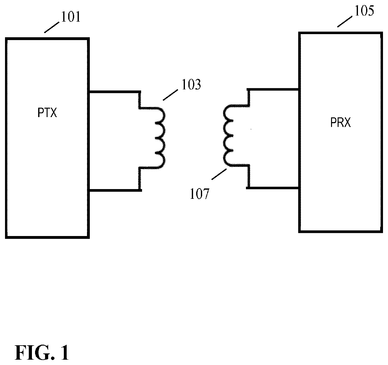
[0070]FIG. 1 illustrates an example of a power transfer system in accordance with some embodiments of the invention. The power transfer system comprises a power transmitter 101 which includes (or is coupled to) a transmitter coil / inductor 103. The system further comprises a power receiving device 105 which includes (or is coupled to) a receiver coil / inductor 107.

[0071]The system provides a wireless inductive power transfer from the power transmitter 101 to the power receiving device 105. Specifically, the power transmitter 101 generates a wireless inductive power transfer signal (also referred to as a power transfer signal, power transfer sig...


PUM


Abstract

A wireless power transfer system includes a power receiver (105) receiving a power transfer from a power transmitter (101) via a wireless inductive power transfer signal. The power transmitter (101) comprises a transmit power coil (103) generating the power transfer signal. A test signal coil (209) coupled to a test signal generator (211) generates a magnetic test signal. A plurality of spatially distributed detection coils (213) is coupled to measurement unit (215) generating a set of measurement values reflecting signals induced in the detection coils (213) by the magnetic test signal. A processor (217) determines a measurement spatial distribution of the measurement value where the spatial distribution reflects positions of the detection coils (213). A foreign object detector (219) detects a presence of a foreign object in response to a comparison of the measurement spatial distribution to a reference spatial distribution. The foreign object detector (219) is arranged to determine the reference spatial distribution in response to data received from the power receiving device (105).

Description

FIELD OF THE INVENTION[0001]The invention relates to foreign object detection in an inductive power transfer system and in particular, but not exclusively, to foreign object detection for a power transmitter providing inductive power transfer using elements compatible with the Qi Specifications for wireless power transfer systems.BACKGROUND OF THE INVENTION[0002]Most present day systems require a dedicated electrical contact in order to be powered from an external power supply. However, this tends to be impractical and requires the user to physically insert connectors or otherwise establish a physical electrical contact. Typically, power requirements also differ significantly, and currently most devices are provided with their own dedicated power supply resulting in a typical user having a large number of different power supplies with each power supply being dedicated to a specific device. Although, the use of internal batteries may avoid the need for a wired connection to a power s...

Claims


Application Information

Patent Timeline
Patent Type & Authority Applications(United States)
IPC IPC(8): H02J50/12G01R27/26G01R31/42H02J50/60
CPCH02J50/60H02J50/12G01R31/42G01R27/2611H02J50/10H02J50/005
Inventor VAN WAGENINGEN, ANDRIESSTARING, ANTONIUS ADRIAAN MARIAETTES, WILHELMUS GERARDUS MARIAFRISSEN, PETRUS CAROLUS MARIAMEHENDALE, ADITYAPOTZE, WILLEM
Owner KONINKLJIJKE PHILIPS NV
Learn More