
Fluid treatment reactor

a technology of fluid treatment reactor and reactor, which is applied in the direction of specific water treatment objectives, chemistry apparatus and processes, and diseases, etc., can solve the problems of virtually destroying or rendering substantially harmless the dna of many, substantially prohibiting the growth and/or reproduction of microorganisms, and virtually destroying them or destroying them. , to achieve the effect of reducing the amount of photons reflected

Active Publication Date: 2020-10-22
CRYSTAL
View PDF0 Cites 4 Cited by
  • Summary
  • Abstract
  • Description
  • Claims
  • Application Information

AI Technical Summary

Benefits of technology

The patent is about an optical coupler that connects an LED chip to a chamber. The coupler has a curved end that reduces the amount of light that bounces back from the coupler and the fluid it's in. This invention helps improve the efficiency of the optical coupling.

Problems solved by technology

Exposure to certain wavelengths of light can disrupt the DNA of many cellular microorganisms—virtually destroying them or rendering them substantially harmless.
The exposure to UV radiation can also substantially prohibit the growth and / or reproduction of microorganisms in the liquid.
A system that uses UV radiation to irradiate fluids is often known in the art as a “UV reactor.” Undesirably, conventional UV reactors typically suffer from various disadvantages.
Specifically, UV light is difficult to extract efficiently from UV light sources, such as light-emitting diodes (LEDs).
Additionally, conventional UV reactors often only successfully utilize a fraction of the UV output of such light sources for disinfection (i.e., only a small fraction of emitted UV light is successfully introduced into the liquid to be treated).
In addition, UV LEDs often generate a significant amount of heat, particularly since they must frequently be operated at higher currents (generating larger output fluxes) to compensate for inefficient light extraction.

Method used


Image

  • Fluid treatment reactor
  • Fluid treatment reactor
  • Fluid treatment reactor

Examples


Embodiment Construction

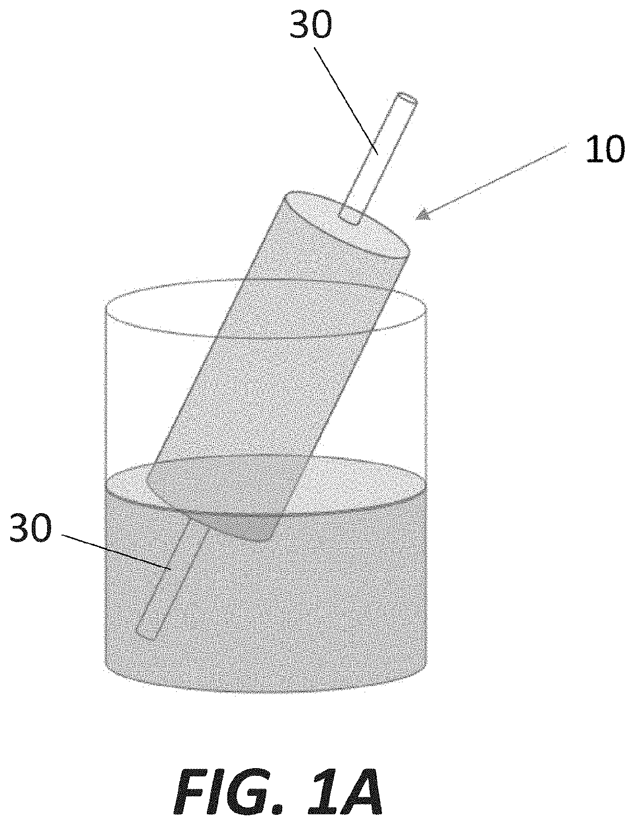
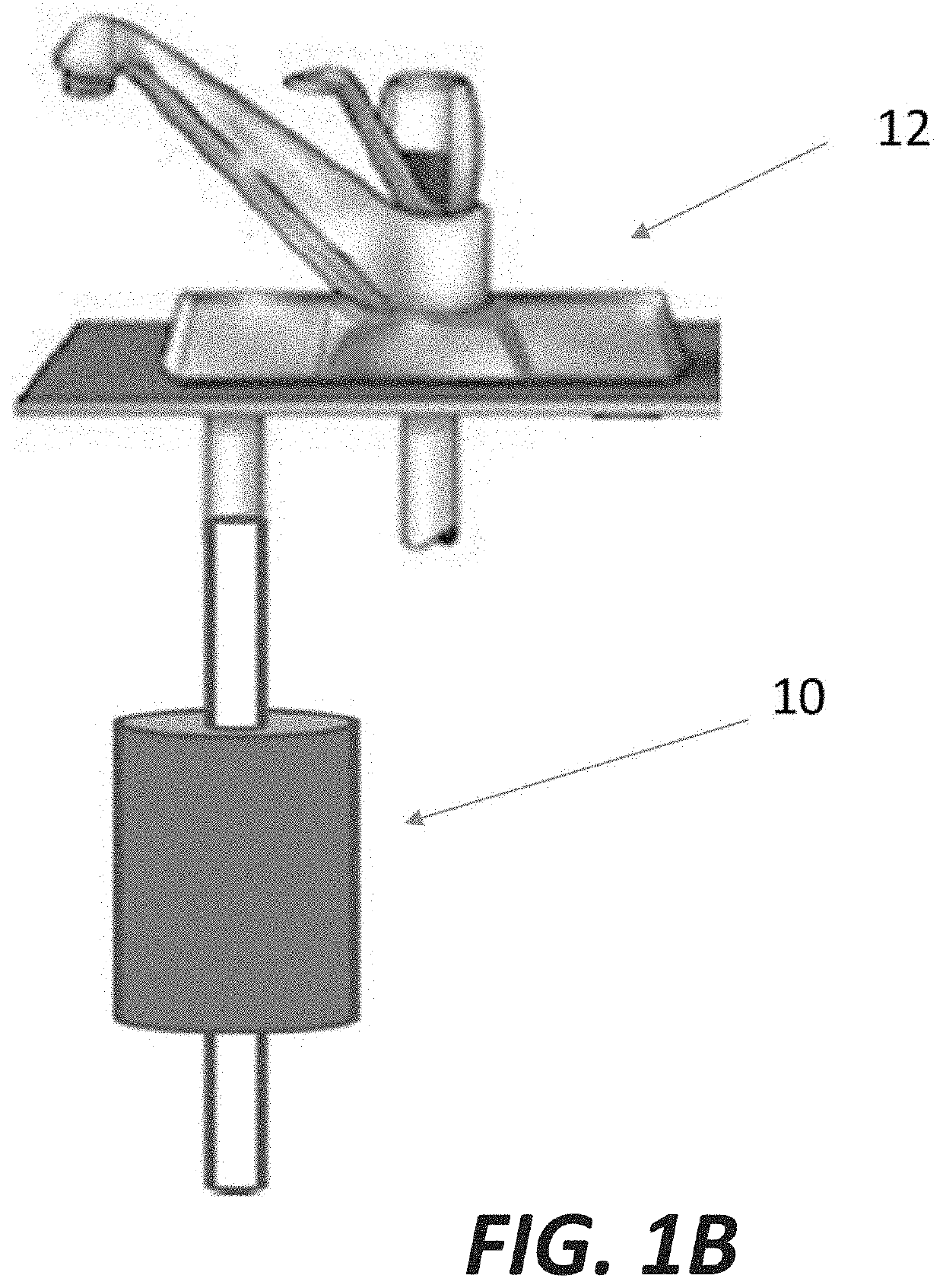
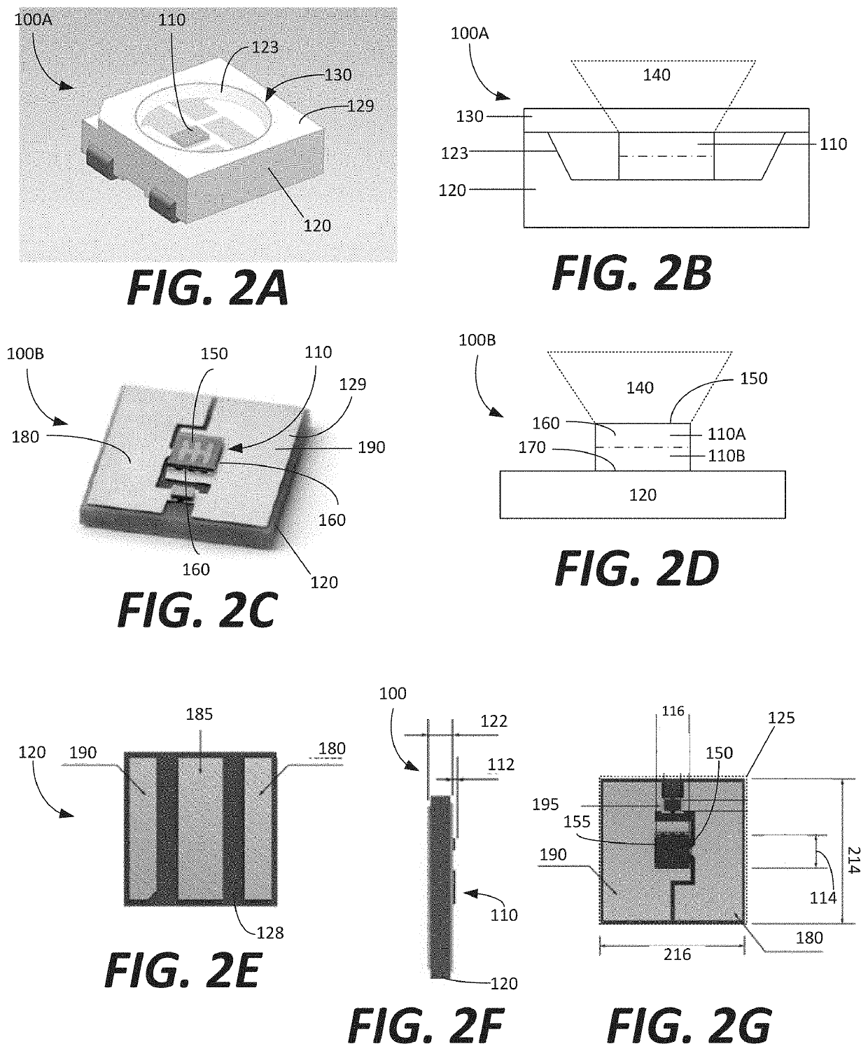
[0005]In accordance with one embodiment of the invention, a system for disinfecting fluid includes a UVC LED. The UVC LED includes an LED chip configured to emit UVC radiation and a package coupled with the LED chip. The LED chip has a top surface that defines a chip top surface area. The top surface is formed from a semiconductor material having an index of refraction. The fluid reactor has at least one wall that defines a chamber configured to contain the fluid. The at least one wall has an aperture configured to receive UVC radiation into the chamber. The aperture extends through the at least one wall. The aperture has an aperture area that is (1) smaller than a top surface area of the package and (2) equal to or larger than the chip top surface area.

[0006]The UVC LED may be of the type having an exposed top surface. Alternatively, the UVC LED may be on the type having a lidded top surface. The system may be configured to couple more than 60% of the total output radiation of the ...


PUM


Abstract

A system for disinfecting fluid includes a UVC LED. The UVC LED includes an LED chip configured to emit UVC radiation and a package coupled with the LED chip. The LED chip has a top surface that defines a chip top surface area. The top surface is formed from a semiconductor material having an index of refraction. The fluid reactor has at least one wall that defines a chamber configured to contain the fluid. The at least one wall has an aperture configured to receive UVC radiation into the chamber. The aperture extends through the at least one wall. The aperture has an aperture area that is (1) smaller than a top surface area of the package and (2) equal to or larger than the chip top surface area.

Description

PRIORITY[0001]This patent application claims priority from provisional U.S. patent application No. 62 / 836,793, filed Apr. 22, 2019, entitled “FLUID TREATMENT REACTOR,” and naming Leo J. Schowalter, Rajul Randive, and Steven Berger as inventors, the disclosure of which is incorporated herein, in its entirety, by reference.FIELD OF THE INVENTION[0002]Various embodiments of the invention generally relate to fluid treatment and, more particularly, various embodiments of the invention relate to using ultraviolet light for water treatment.BACKGROUND OF THE INVENTION[0003]Fluids, including liquid water, are commonly used for many domestic and industrial purposes, such as drinking, food preparation, manufacturing, processing of chemicals, and cleansing. It is often necessary to purify a liquid prior to its use. Filters such as ceramic filters are typically used to remove particulate and chemical impurities from liquids. In addition, a liquid can be exposed to UV radiation to neutralize micr...

Claims


Application Information

Patent Timeline
IPC IPC(8): C02F1/32A61L2/26A61L2/10
CPCA61L2/26A61L2202/11A61L2202/122C02F1/325C02F2303/04A61L2/10C02F2201/3222C02F2201/3228C02F2307/10
Inventor SCHOWALTER, LEORANDIVE, RAJULBERGER, STEVEN
Owner CRYSTAL
Learn More