
Energy control system

a technology of energy control system and energy control module, which is applied in the direction of emergency power supply arrangement, battery/fuel cell control arrangement, light to electrical conversion, etc., can solve the problems of inflexibility of existing system in energy system sizing and load management, and achieve the effect of reducing installation time and cost, increasing flexibility and simplicity, and reducing cost to the end user

Active Publication Date: 2020-10-22
SUNPOWER CORPORATION
View PDF0 Cites 2 Cited by
  • Summary
  • Abstract
  • Description
  • Claims
  • Application Information

AI Technical Summary

Benefits of technology

The patent describes energy control systems for whole home and partial home backup with integrated breaker spaces and metering. The systems have unique hardware features and software functionalities to provide advanced control application functions to customers with two types of service panels. The systems can provide separate and metered generation and load panels, as well as integrated and controllable electrical vehicle (EV) charging. The systems can also provide flexibility and simplicity during installation, reduced installation time and cost, an aesthetically pleasing design, and reduced cost to the end-user. The patent also describes a controller that can decrease the charging or discharging rate of a battery based on its current state of charge. The load consumption data can also trigger increases or decreases in the charging or discharging rate of the battery.

Problems solved by technology

Some existing energy control systems may only offer partial home backup and may require the user to select loads to wire to a separate load panel that are powered through the inverter at all times. Other systems provide whole home and partial home backup through a central disconnect, but require multiple subpanel boxes and have limited controls.
Furthermore, existing systems do not offer flexibility in energy system sizing and load management.

Method used


Image

  • Energy control system
  • Energy control system
  • Energy control system

Examples


Embodiment Construction

[0094]Embodiments of the present disclosure are described in detail with reference to embodiments thereof as illustrated in the accompanying drawings. References to “one embodiment,”“an embodiment,”“some embodiments,”“certain embodiments,” etc., indicate that the embodiment described may include a particular feature, structure, or characteristic, but every embodiment may not necessarily include the particular feature, structure, or characteristic. Moreover, such phrases are not necessarily referring to the same embodiment. Further, when a particular feature, structure, or characteristic is described in connection with an embodiment, it is submitted that it is within the knowledge of one skilled in the art to affect such feature, structure, or characteristic in connection with other embodiments whether or not explicitly described.

[0095]The term “about” or “substantially” or “approximately” as used herein refer to a considerable degree or extent. When used in conjunction with, for exa...


PUM


Abstract

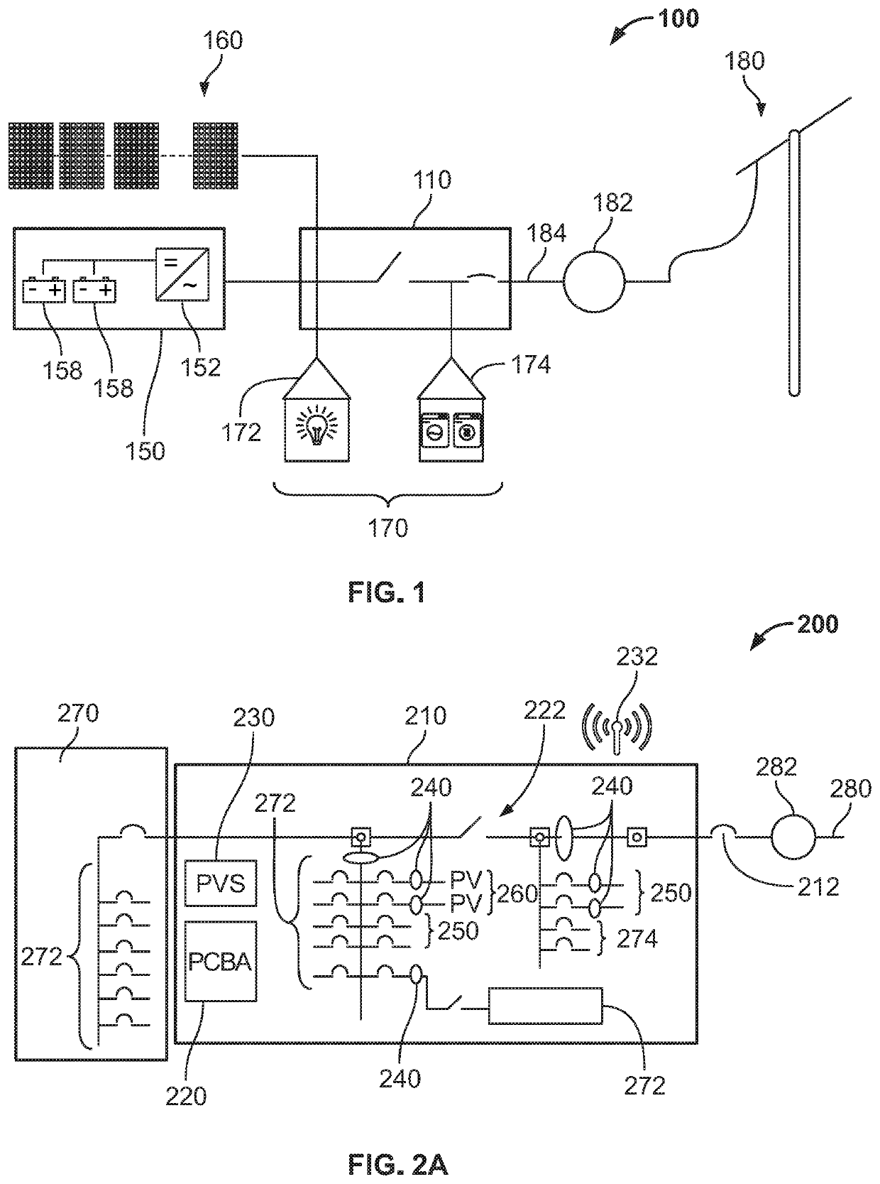
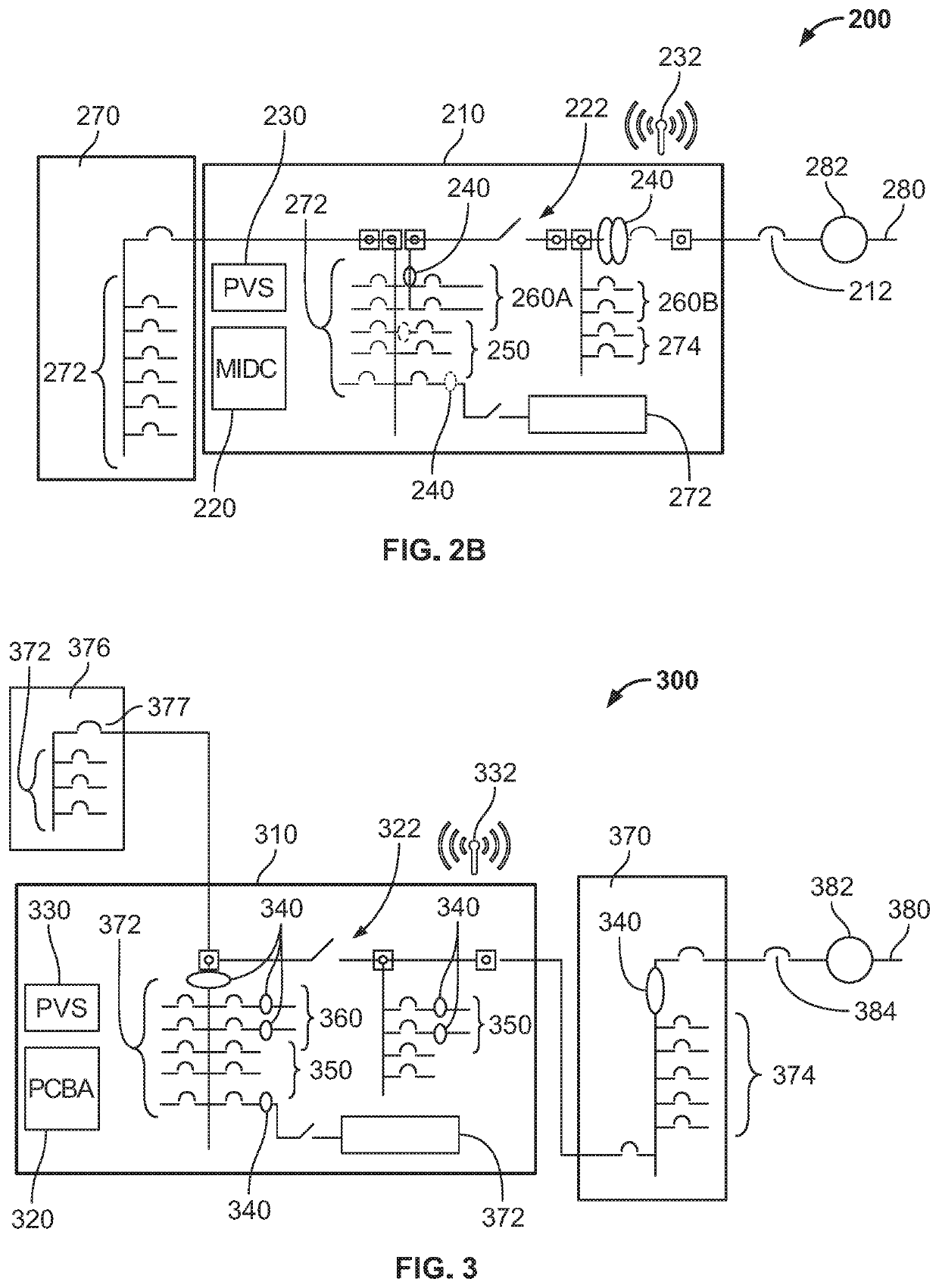
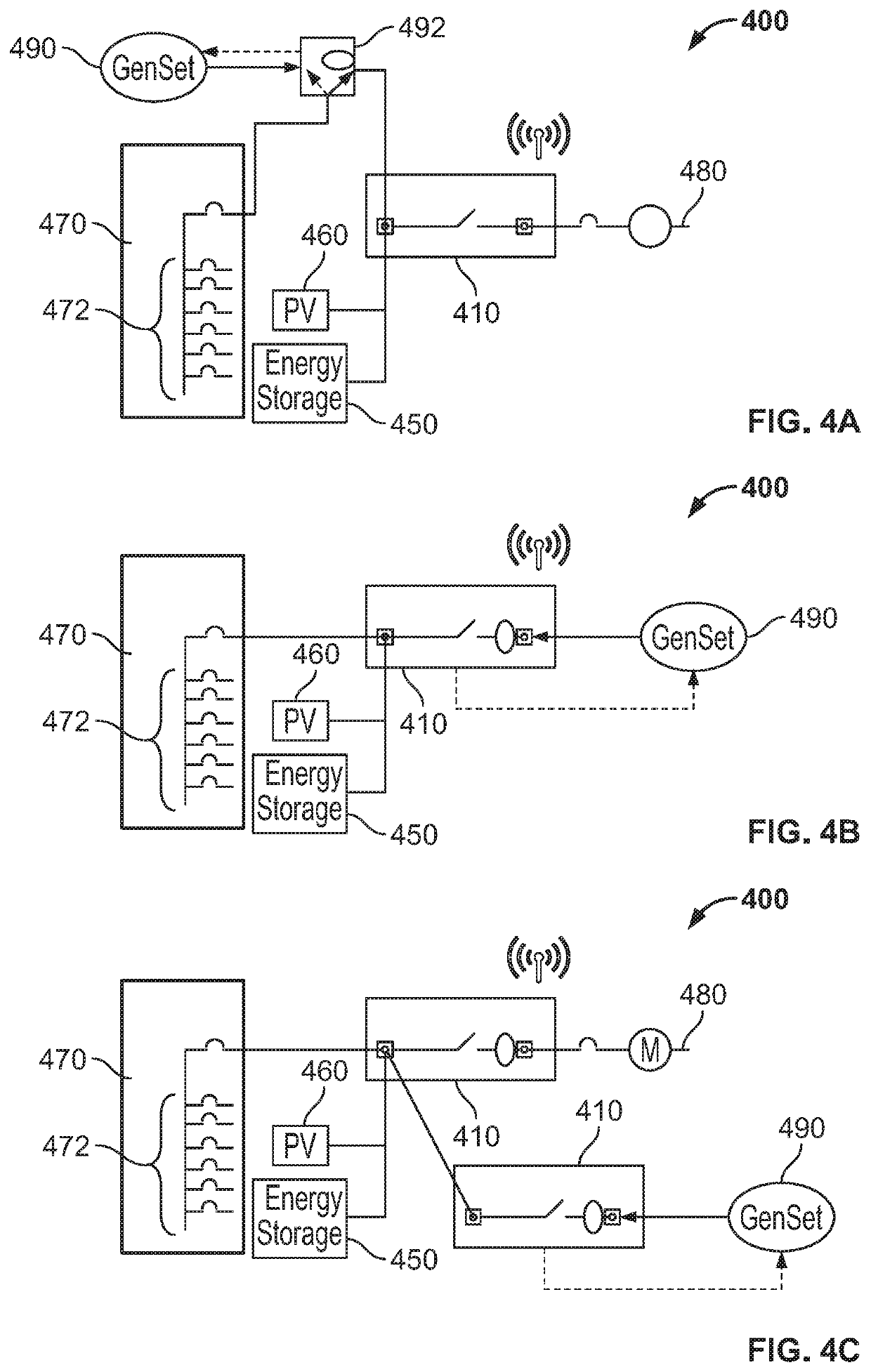
The present disclosure provides energy control systems for whole home and partial home backup with integrated breaker spaces and metering. The energy control system includes a grid interconnection electrically coupled to a utility grid, a backup power interconnection electrically coupled to a backup power source, a backup load interconnection electrically coupled to at least one backup load, and a non-backup load interconnection electrically coupled to at least one non-backup load. The energy control system includes a microgrid interconnection device that switches between an on-grid mode to electrically connect the grid interconnection and the backup power interconnection with the backup and non-backup load interconnections and a backup mode to electrically disconnect the grid interconnection and the non-backup load interconnection from the backup power interconnection.

Description

CROSS-REFERENCE TO RELATED APPLICATIONS AND INCORPORATION BY REFERENCE[0001]This application claims priority to U.S. Provisional Patent Application No. 62 / 836,494, filed on Apr. 19, 2019; U.S. Provisional Patent Application No. 62 / 884,808, filed Aug. 9, 2019; U.S. Provisional Patent Application No. 62 / 903,526, filed Sep. 20, 2019; which are incorporated by reference herein in their entirety for all purposes.FIELD[0002]The present disclosure relates to energy control systems. In particular, embodiments relate to energy control systems for solar electric systems, for example, solar electric systems for residential buildings.BACKGROUND[0003]Some existing energy control systems may only offer partial home backup and may require the user to select loads to wire to a separate load panel that are powered through the inverter at all times. Other systems provide whole home and partial home backup through a central disconnect, but require multiple subpanel boxes and have limited controls. Fur...

Claims


Application Information

Patent Timeline
Patent Type & Authority Applications(United States)
IPC IPC(8): H02J9/06H02J3/38H02J7/00H02J3/00B60L8/00B60L50/60B60L58/12B60L58/18
CPCB60L8/003H02J9/06H02J7/0013H02J3/004H02J7/0048B60L58/12H02J2300/24B60L58/18H02J7/007B60L50/66H02J3/381B60L53/51B60L53/60Y02E10/56H02J2300/20H02J2310/60H02J9/062H02J2310/12H02J2310/14Y02B10/10Y02B70/30Y02B70/3225Y02T10/70Y02T10/7072Y02T90/12Y04S20/242Y04S20/222H02J2310/66B60L50/60
Inventor NARLA, SANDEEPKUHN, BRIANFISCHER, KEVIN C.UEBEL, UDOROBINSON, MARC A.
Owner SUNPOWER CORPORATION
Learn More