
Method for evaluating an inflow on a rotor blade of a wind turbine, method for controlling a wind turbine, and a wind turbine

a technology for wind turbines and rotor blades, which is applied in the direction of wind turbines, mechanical equipment, machines/engines, etc., can solve the problems of large gradients, large noise at sites with particularly large gradients, and large nois

Inactive Publication Date: 2020-11-05
WOBBEN PROPERTIES GMBH
View PDF0 Cites 6 Cited by
  • Summary
  • Abstract
  • Description
  • Claims
  • Application Information

AI Technical Summary

Benefits of technology

The patent aims to reduce the intensity of low-frequency noise that is felt when a blade passes through a certain frequency. The goal is to make this noise effect as small as possible, as early as possible.

Problems solved by technology

The noise substantially arises at sites that have particularly large gradients in the wind speed over the rotor disk.
Such OAM noise can also arise under certain atmospheric conditions, which likewise cause large gradients.
If the angle of attack exceeds a certain critical value, there is a spontaneous separation of the boundary layer, which also has great effects on the volume and characteristic of the aeroacoustic noise of a wind power installation.
On the other hand, it is undesirable as a matter of principle to throttle the power or rotational speed and this should therefore be carried out as little as possible.
However, such a detection in the far field is complicated and can only detect the noise once it has already occurred.

Method used


Image

  • Method for evaluating an inflow on a rotor blade of a wind turbine, method for controlling a wind turbine, and a wind turbine
  • Method for evaluating an inflow on a rotor blade of a wind turbine, method for controlling a wind turbine, and a wind turbine
  • Method for evaluating an inflow on a rotor blade of a wind turbine, method for controlling a wind turbine, and a wind turbine

Examples


Embodiment Construction

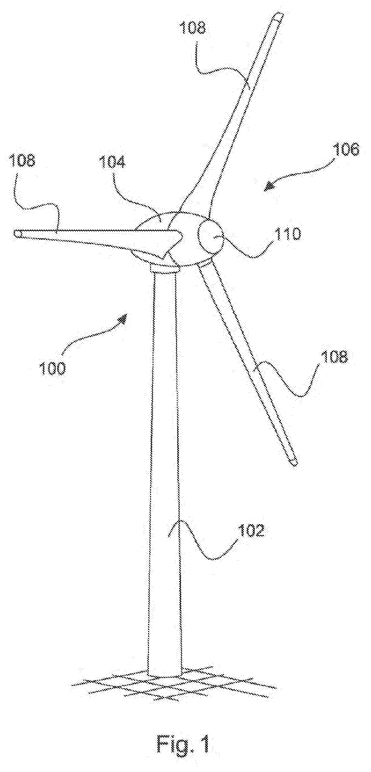
lass="d_n">[0104]FIG. 1 shows a wind power installation 100 having a tower 102 and a nacelle 104. A rotor 106 with three rotor blades 108 and a spinner 110 is arranged at the nacelle 104. During operation, the rotor 106 is put into a rotational movement by the wind and thereby drives a generator in the nacelle 104.

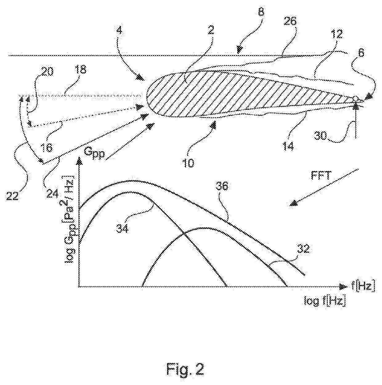
[0105]FIG. 2 shows a profile 2 of a rotor blade at a position relevant to the disclosure. The profile, and hence also the rotor blade, has a blade leading edge 4 and a blade trailing edge 6. Moreover, the profile, and, naturally, the rotor blade as well, has a suction side 8 and a pressure side 10. During the operation of the installation in the case of laminar flow conditions, a boundary layer 12 and 14, respectively, forms on both the suction side 8 and the pressure side 10, which can also be referred to as upper and lower side, respectively. These two illustrated boundary layers 12 and 14 belong to an incident flow, which sets in with substantially laminar flow during a...


PUM


Abstract

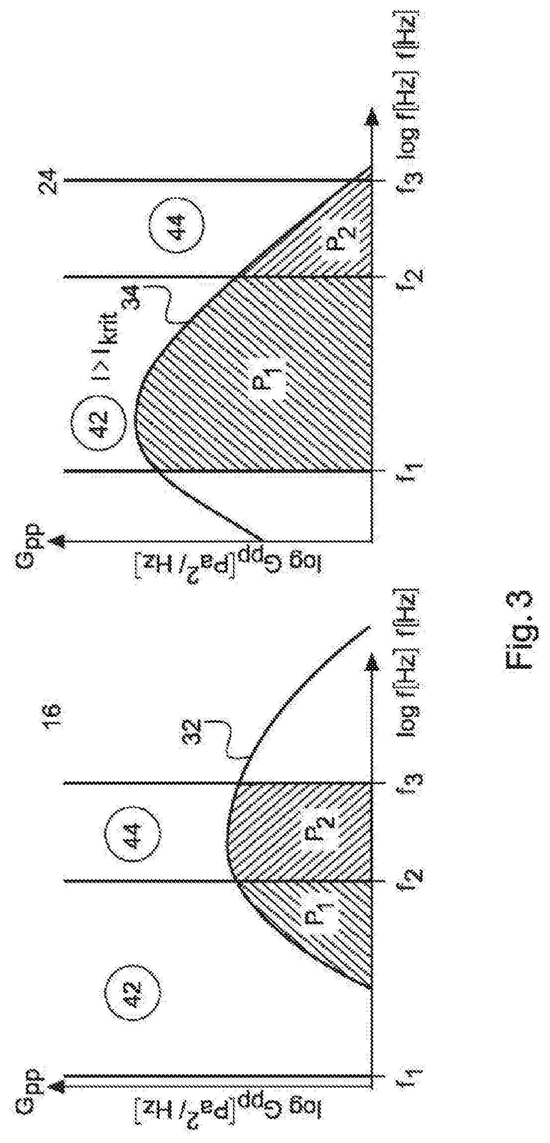
A method for determining an incident flow at a rotor blade of a wind power installation is provided. The method includes recording at least part of a pressure spectrum of pressure, in particular wall pressure, at the rotor blade at at least one measurement position. The method includes determining at least two characteristic values from the pressure spectrum, determining an indicator value from a relationship between the at least two characteristic values and assessing whether a critical incident flow is present depending on the indicator value.

Description

BACKGROUNDTechnical Field[0001]The present invention relates to a method for evaluating an incident flow at a rotor blade of a wind power installation. Moreover, the present invention relates to a method for operating a wind power installation. The invention also relates to a wind power installation.Description of the Related Art[0002]Wind power installations are known and frequently set up. A so-called OAM (“other amplitude modulation”) noise arises at some sites. The noise substantially arises at sites that have particularly large gradients in the wind speed over the rotor disk. Such OAM noise can also arise under certain atmospheric conditions, which likewise cause large gradients. The assumption is made that very large angles of attack occur on the rotor blade when the blade passes through the so-called 12 o'clock position, i.e., stands perpendicularly upward, as result of substantially higher wind speeds at higher altitudes. Then, a critical incident flow arises. In particular,...

Claims


Application Information

Patent Timeline
Patent Type & Authority Applications(United States)
IPC IPC(8): F03D7/02F03D17/00
CPCF03D7/0224F03D7/0276F03D17/00F03D7/0296F03D7/028F03D7/0256F05B2270/301F05B2270/324F05B2270/333F05B2270/804Y02E10/72
Inventor NAPIERALA, CHRISTIAN FRANK
Owner WOBBEN PROPERTIES GMBH
Learn More