
Electric conductivity-measuring material, electric conductivity-measuring film, electric conductivity-measuring device, and electric conductivity-measuring method, as well as electric resistivity-measuring material, electric resistivity-measuring film, electric resistivity-measuring device, and electric resistivity-measuring method

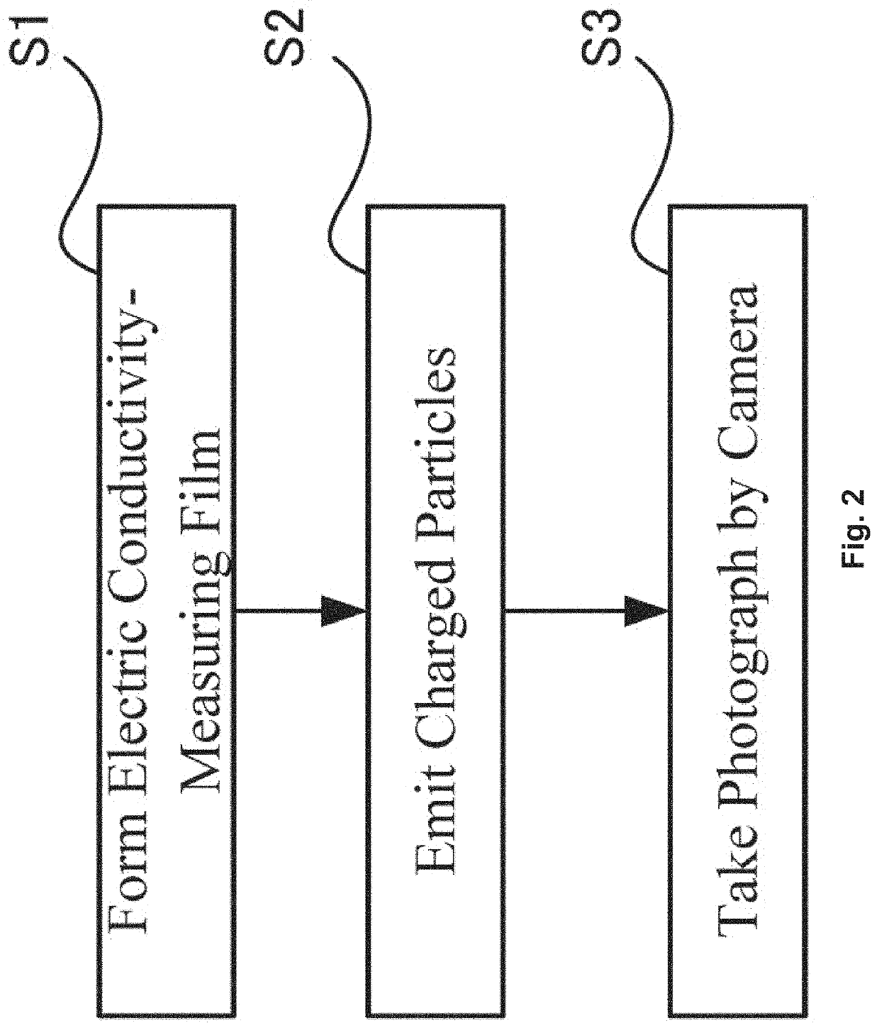
a technology of electric conductivity and measurement method, which is applied in the direction of material analysis using wave/particle radiation, instruments, and material analysis by optical means, etc., can solve the problems of inability to intuitively understand electric conductivity, inability to measure electric conductivity of each portion of the measurement object, and inability to accurately measure electric conductivity. to achieve the effect of convenient measuremen

Active Publication Date: 2020-11-05
NAT INST OF ADVANCED IND SCI & TECH
View PDF2 Cites 2 Cited by
  • Summary
  • Abstract
  • Description
  • Claims
  • Application Information

AI Technical Summary

Benefits of technology

This patent is about a new invention that allows for the measurement of electric conductivity (electroconductivity) and electric resistivity (distribution) on the surface or inside of a measurement object using a special film that emits light based on the electric conductivity of the material it is placed on. This technology can be used in a variety of applications to provide valuable information about the distribution of electric conductivity in a measurement object.

Problems solved by technology

However, the aforementioned conventional electric conductivity-measuring device can measure only average electric conductivity (average conductivity across a certain area (volume)) of a measurement object and cannot measure local electric conductivity of the measurement object, which is a problem.
In other words, electric conductivity of each portion of the measurement object cannot be measured, which is a problem.
Also, when electric conductivity of a large-sized measurement object is measured by the conventional electric conductivity-measuring methods, extremely high voltage must be applied depending on its material so that electric conductivity cannot be actually measured, which is a problem.
Furthermore, the conventional electric conductivity-measuring methods calculates electric conductivity on the basis of voltage applied to a measurement object and current flowing across the measurement object, and thus electric conductivity cannot be intuitively understood, which is a problem.

Method used


Image

  • Electric conductivity-measuring material, electric conductivity-measuring film, electric conductivity-measuring device, and electric conductivity-measuring method, as well as electric resistivity-measuring material, electric resistivity-measuring film, electric resistivity-measuring device, and electric resistivity-measuring method
  • Electric conductivity-measuring material, electric conductivity-measuring film, electric conductivity-measuring device, and electric conductivity-measuring method, as well as electric resistivity-measuring material, electric resistivity-measuring film, electric resistivity-measuring device, and electric resistivity-measuring method
  • Electric conductivity-measuring material, electric conductivity-measuring film, electric conductivity-measuring device, and electric conductivity-measuring method, as well as electric resistivity-measuring material, electric resistivity-measuring film, electric resistivity-measuring device, and electric resistivity-measuring method

Examples


embodiment 1

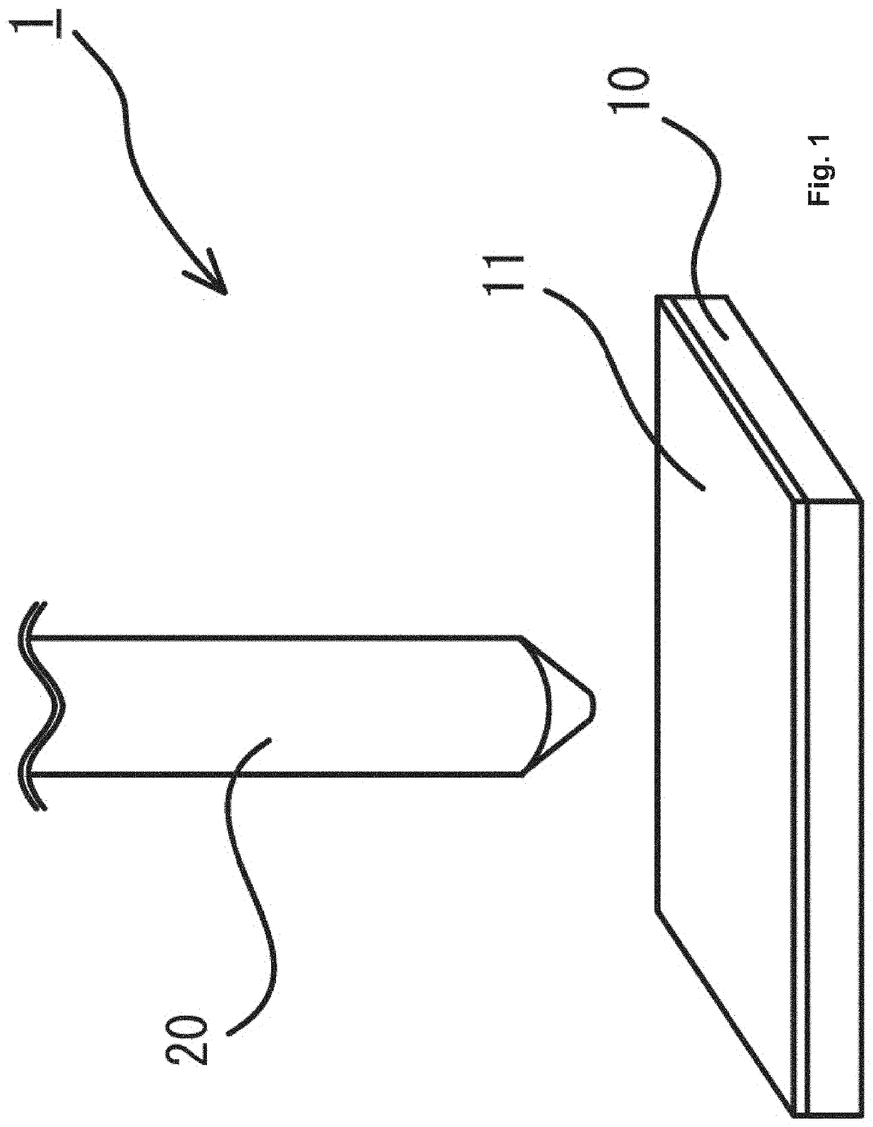
[0095]FIG. 1 illustrates a schematic perspective view of an electric conductivity-measuring device according to Embodiment 1. As illustrated in this figure, in an electric conductivity-measuring device 1 according to Embodiment 1, an electric conductivity-measuring film 11 is formed throughout a surface of a rectangular flat measurement object 10, the electric conductivity-measuring film 11 containing at least one of an fluorescent substance, a luminescent substance, an electroluminescent substance, a breaking luminescent substance, a photochromic substance, an afterglow substance, a photostimulated luminescent substance, and a mechanoluminescent substance.

[0096]In addition, cylindrical charged particle-emitting unit 20 having a taper-shaped tip portion is fixed above the electric conductivity-measuring film 11 by a jig (not shown) so that the electric conductivity-measuring film 11 can be irradiated with charged particles. Specifically, when an electric field (or voltage) is applie...

example 1

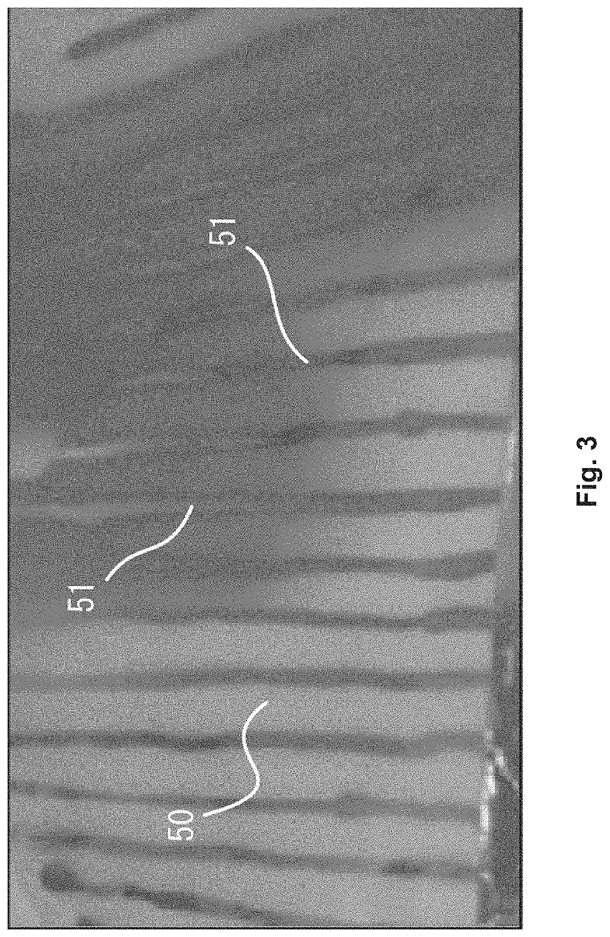
[0114]As shown in FIG. 3, a plurality of silver nanoink lines were formed on a polylactic acid sheet (PLA sheet) by using silver ink (DGP-NO, from Advanced Nano Products Co., Ltd). Then, a PLA sheet 50 on which the silver nanoink lines 51 were formed in a stripe shape was made as a measurement object.

[0115]Then, an electric conductivity-measuring film, i.e., non-woven fabric (electric conductivity-measuring sheet 53) into which SrAl2O4:Eu2+ was kneaded was placed on this PLA sheet 50. Next, as shown in FIG. 4, an electrode 55 as a charged particle-emitting unit was placed above the non-woven fabric (distance: 10 mm).

[0116]Thereafter, the measurement object was irradiated with charged particle by applying DC voltage of 3 kV and 1 μA to the electrode 55 to cause corona discharge, the result being shown in FIG. 5. Here, electric conductivity of the PLA sheet is 1.00×10⁻¹⁵Ω−1·m−1 or more, and electric conductivity of the silver nanoink lines is 1.68×10⁻²Ω−1·m−1.

[0117]As shown in FIG. 5,...

example 2

[0118]As shown in FIG. 6, an electric conductivity-measuring film, i.e., non-woven fabric (electric conductivity-measuring sheet) into which SrAl2O4:Eu2+ was kneaded was placed on a packaging box (measurement object) with characters and the like printed on it. Here, portions with characters printed have higher electric conductivity than portions without characters printed.

[0119]Then, as in Example 1, the measurement object was irradiated with charged particle by applying voltage / current (3 k, 1 μA) to an electrode located above (distance: 10 mm) to cause corona discharge. The results are shown in FIGS. 7 and 8. FIG. 7 is a photograph just after the measurement objectwas irradiated with charged particles, and FIG. 8 is a photograph after a while since the measurement object was irradiated with the charged particles.

[0120]As can be seen from these figures, portions of the electric conductivity-measuring film corresponding to the printed characters and the like momentarily emitted ligh...


PUM

PropertyMeasurementUnit
thicknessaaaaaaaaaa
thicknessaaaaaaaaaa
distanceaaaaaaaaaa

Abstract

[Object] An electric conductivity-measuring material which emits light according to electric conductivity of a measurement object; an electric conductivity-measuring film containing the material; and an electric conductivity-measuring device and an electric conductivity-measuring method using the electric conductivity-measuring film are provided. An electric resistivity-measuring material which emits light according to electric resistivity of a measurement object when electrons are made incident; an electric resistivity-measuring film containing the material; and an electric resistivity-measuring device and an electric resistivity-measuring method using the electric resistivity-measuring film are also provided.[Solution] An electric conductivity-measuring material is used, which contains at least one of a fluorescent substance, a luminescent substance, an electroluminescent substance, a fractoluminescent substance, a photochromic substance, an afterglow substance, a photostimulated luminescent substance and a mechanoluminescent substance.

Description

TECHNICAL FIELD[0001]The present invention relates to an electric conductivity-measuring material capable of measuring electric conductivity of a surface and inside of an article such as various components, as well as an electric conductivity-measuring film, an electric conductivity-measuring device, and an electric conductivity-measuring method using the material. The present invention also relates to an electric resistivity-measuring material capable of measuring electric resistivity of a surface and inside of an article such as various components, as well as an electric resistivity-measuring film, an electric resistivity-measuring device, and an electric resistivity-measuring method using the material.BACKGROUND ART[0002]Electric conductivity (electroconductivity) is one of physical property values representing properties of a substance. Electric conductivity represents the ease with which electricity flows (the reciprocal of electric resistivity) and its value varies from substa...

Claims


Application Information

Patent Timeline
Patent Type & Authority Applications(United States)
IPC IPC(8): G01N21/76G01N21/66G01R27/02G01N21/70C09K11/77
CPCG01N2021/634G01N21/76G01N21/66G01R27/02G01N21/70C09K11/7734G01N23/2254Y02A90/30
Inventor TERASAKI, NAOKIKUNAGA, KAZUYA
Owner NAT INST OF ADVANCED IND SCI & TECH
Learn More