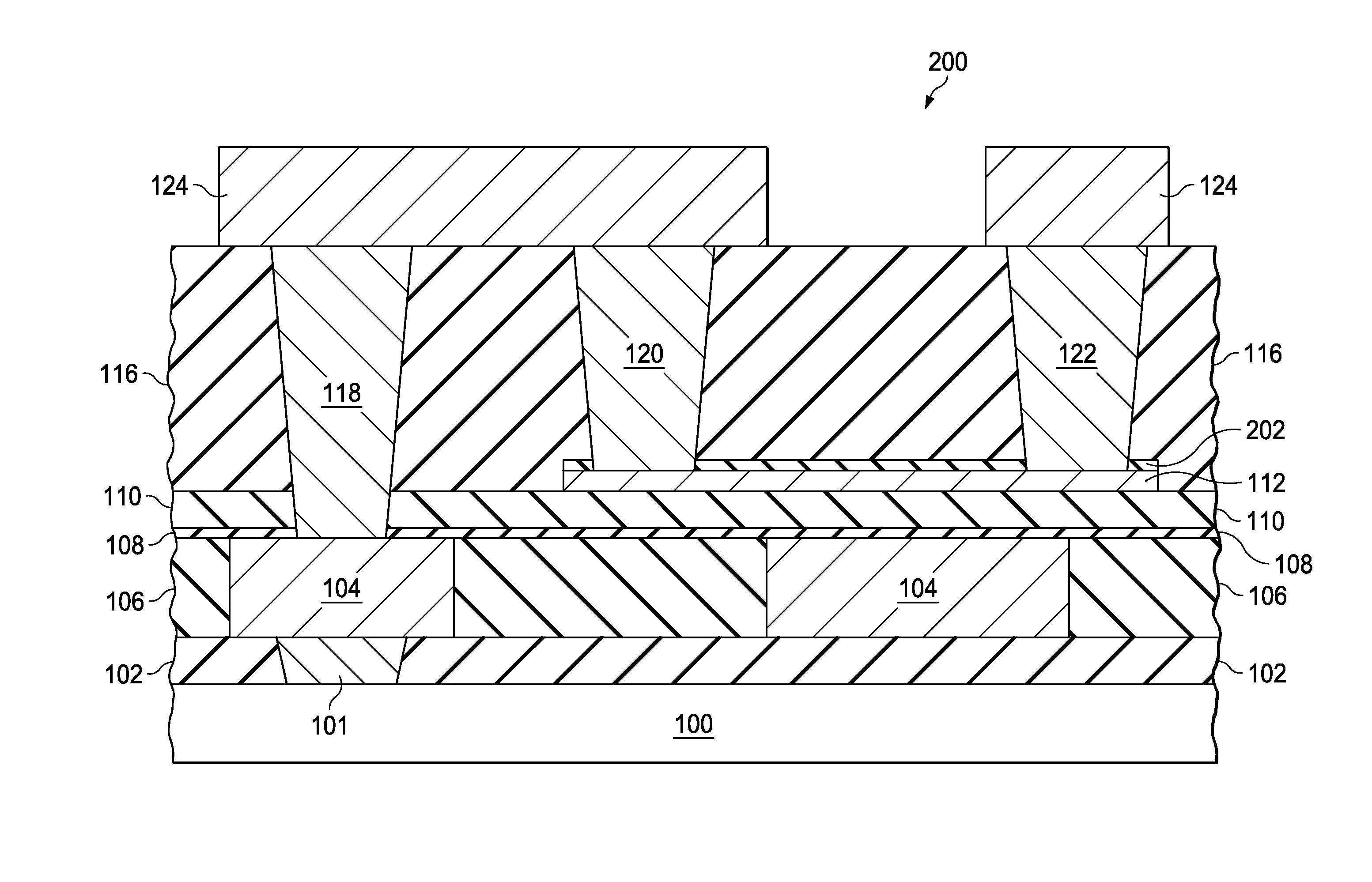
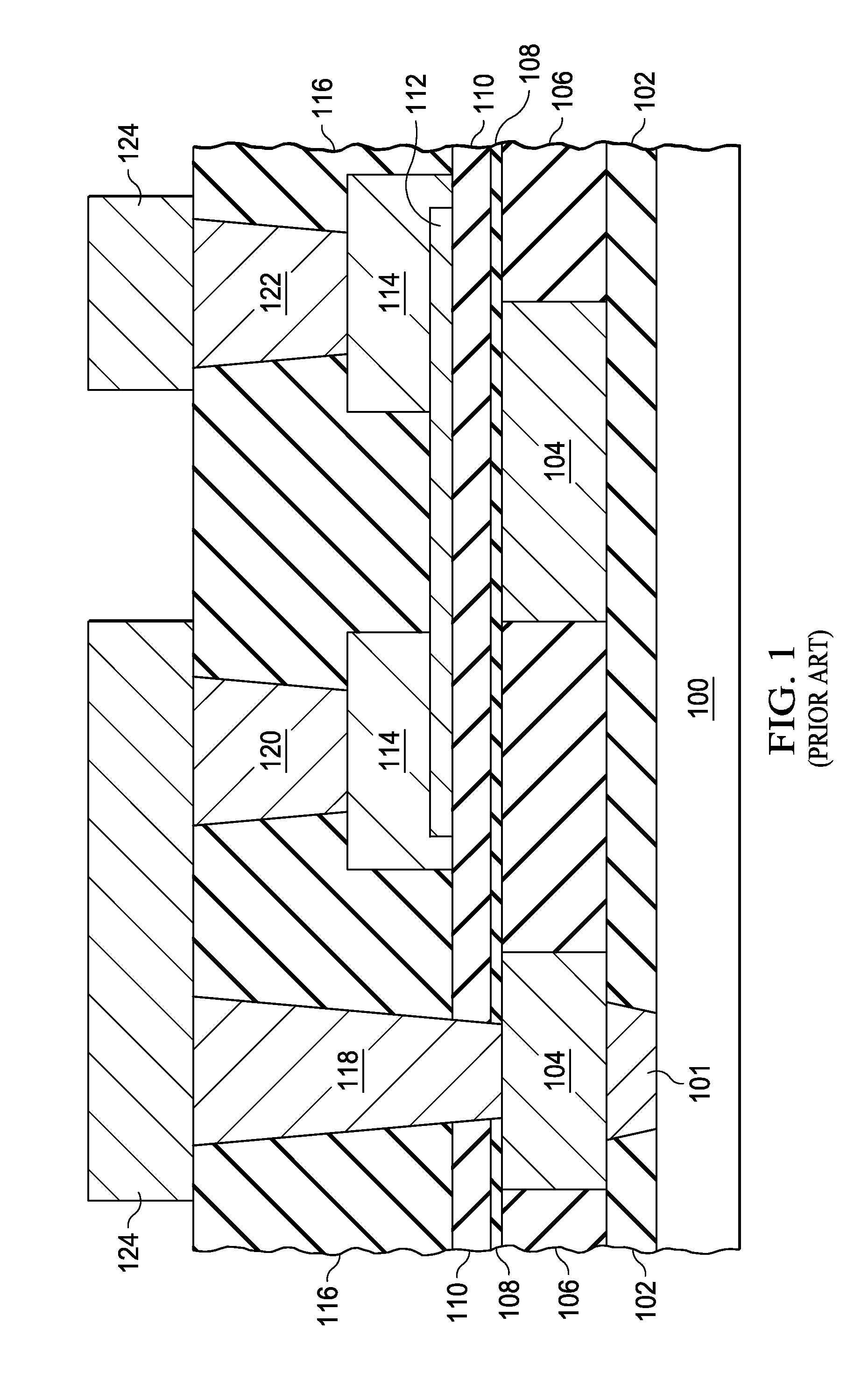
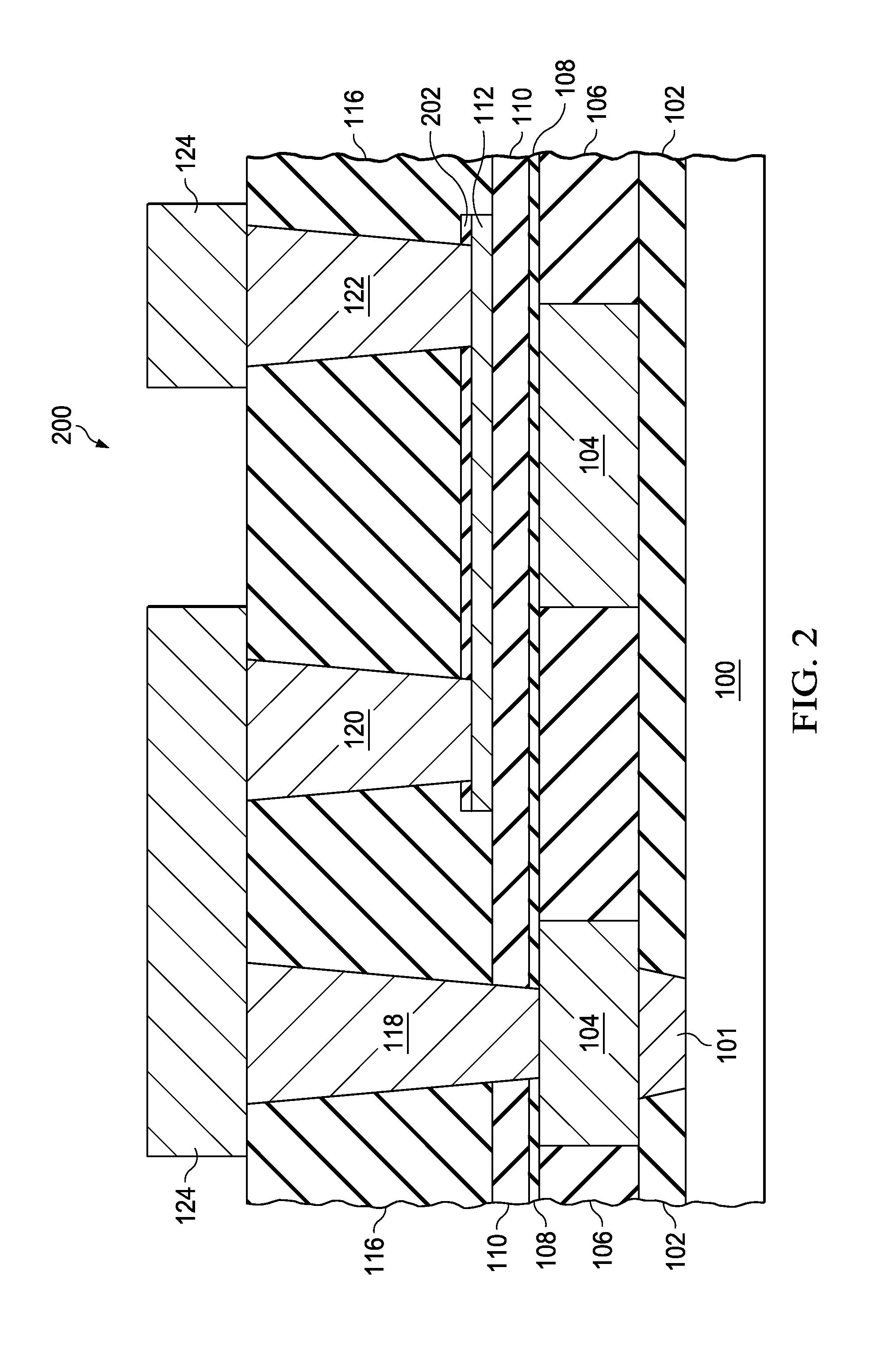
Metal thin film resistor and process

a technology of metal thin film and resistor, which is applied in the direction of semiconductor devices, semiconductor/solid-state device details, electrical equipment, etc., can solve the problems of adding cost and cycle time, adding considerable expense and cycle time to the manufacturing flow,

Active Publication Date: 2015-07-02
TEXAS INSTR INC
View PDF3 Cites 19 Cited by
  • Summary
  • Abstract
  • Description
  • Claims
  • Application Information

AI Technical Summary

Benefits of technology

[0007]The following presents a simplified summary in order to provide a basic understanding of one or more aspects of the invention. This summary is not an extensive overview of the invention, and is neither intended to identify key or cri...

Problems solved by technology

Integrating a metal thin film resistor in the BEOL of an integrated circuit manufacturing flow adds cost and cycle time.
The cost of 3 additional lithography steps ...

Method used


Image

  • Metal thin film resistor and process
  • Metal thin film resistor and process
  • Metal thin film resistor and process

Examples


Embodiment Construction

[0013]The present invention is described with reference to the attached figures, wherein like reference numerals are used throughout the figures to designate similar or equivalent elements. The figures are not drawn to scale and they are provided merely to illustrate the invention. Several aspects of the invention are described below with reference to example applications for illustration. It should be understood that numerous specific details, relationships, and methods are set forth to provide an understanding of the invention. One skilled in the relevant art, however, will readily recognize that the invention can be practiced without one or more of the specific details or with other methods. In other instances, well-known structures or operations are not shown in detail to avoid obscuring the invention. The present invention is not limited by the illustrated ordering of acts or events, as some acts may occur in different orders and / or concurrently with other acts or events. Furth...


PUM


Abstract

An integrated circuit with a metal thin film resistor with an overlying etch stop layer. A process for forming a metal thin film resistor in an integrated circuit with the addition of one lithography step.

Description

CROSS-REFERENCE TO RELATED APPLICATIONS[0001]This application claims the benefit of priority under U.S.C. §119(e) of U.S. Provisional Application 61 / 922,155 (Texas Instruments docket number TI-68478, filed Dec. 31, 2013.)FIELD OF THE INVENTION[0002]This invention relates to the field of integrated circuits. More particularly, this invention relates to forming a metal thin film resistor within the interconnect layers in integrated circuits.BACKGROUND OF THE INVENTION[0003]Metal thin film resistors are well known and may be formed using a variety of resistive metals. Nichrome (NiCr) and sichrome (CrSi) are two that are commonly used. These types of thin-film resistors are formed in the back end (BEOL) of an integrated circuit manufacturing flow. BEOL resistors have less parasitic capacitance than resistors (typically polysilicon, silicide, or nwell) formed in the front end of line (FEOL) since they are formed at a greater distance from the substrate. BEOL resistors are preferred for h...

Claims


Application Information

Patent Timeline
IPC IPC(8): H01L21/768H01L23/528H01L23/532H01L23/522
CPCH01L21/7681H01L23/5228H01L21/76834H01L23/5329H01L23/528H01L23/53261H01L23/5226H01L23/53223H01L23/53295H01L2924/0002H01L28/24H01L2924/00
Inventor ALI, ABBASBEACH, ERIC
Owner TEXAS INSTR INC
Why Eureka
Try Eureka