
Dual mode sensing joystick assembly

a joystick and dual-mode technology, applied in the field of joysticks, can solve the problems of difficulty in controlling fine movements and/or working in tight spaces, requirement of functional safety requirements, and resistance of operators, so as to improve control, improve the effect of starting/stopping the action of the joystick, and improve the effect of safety

Active Publication Date: 2020-11-12
SENSATA TECHNOLOGIES INC
View PDF3 Cites 2 Cited by
  • Summary
  • Abstract
  • Description
  • Claims
  • Application Information

AI Technical Summary

Benefits of technology

The patent text describes a need for better control and safety in joysticks used in various applications such as fighter jets, backhoes, and video games. The subject technology provides a solution by using different sensors for position and force to avoid common failures and improve safety. This technology can be combined with other haptic mechanisms and is applicable to various joystick applications. Additionally, it is easy to calibrate and can help reduce production cost.

Problems solved by technology

Some resistance exists because of controllability deficiencies.
As a result, it can be difficult for operators to control fine movements and / or work in tight spaces.
Another problem of electronic vehicle controls is the requirement of functional safety requirements.
However, if the redundant sensor is the same technology as the primary sensor, common cause failures can result.
For example, parasitic magnetic fields could prevent proper operation of both sensor systems.
Further, the position sensors and the force sensors provide plausibility checks on each other.

Method used


Image

  • Dual mode sensing joystick assembly
  • Dual mode sensing joystick assembly
  • Dual mode sensing joystick assembly

Examples


Embodiment Construction

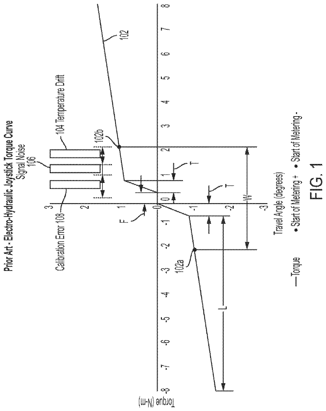
[0024]The subject technology overcomes many of the prior art problems associated with electro-hydraulic joysticks. The advantages, and other features of the technology disclosed herein, will become more readily apparent to those having ordinary skill in the art from the following detailed description of certain preferred embodiments taken in conjunction with the drawings which set forth representative embodiments of the present invention and wherein like reference numerals identify similar structural elements. It is understood that references to the figures such as left and right are with respect to the figures and not meant in a limiting sense.

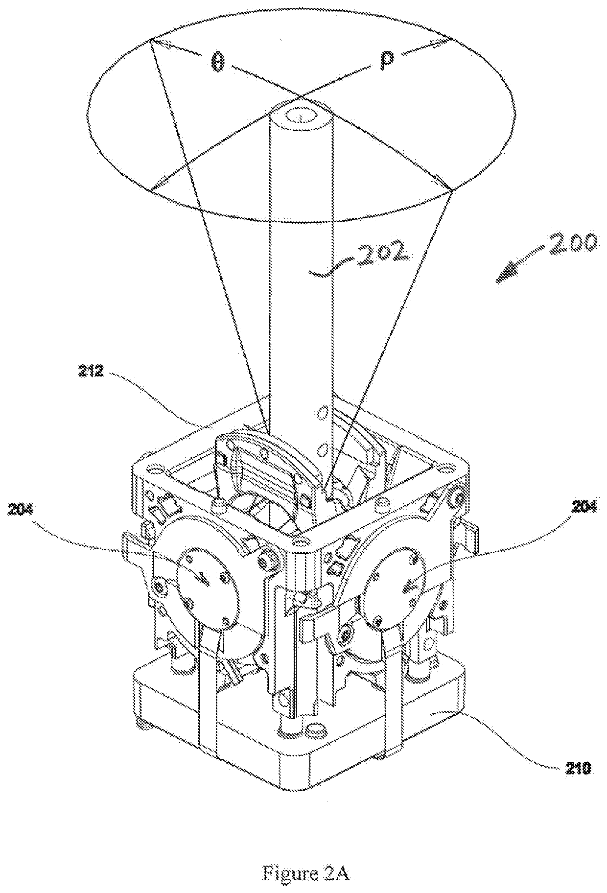
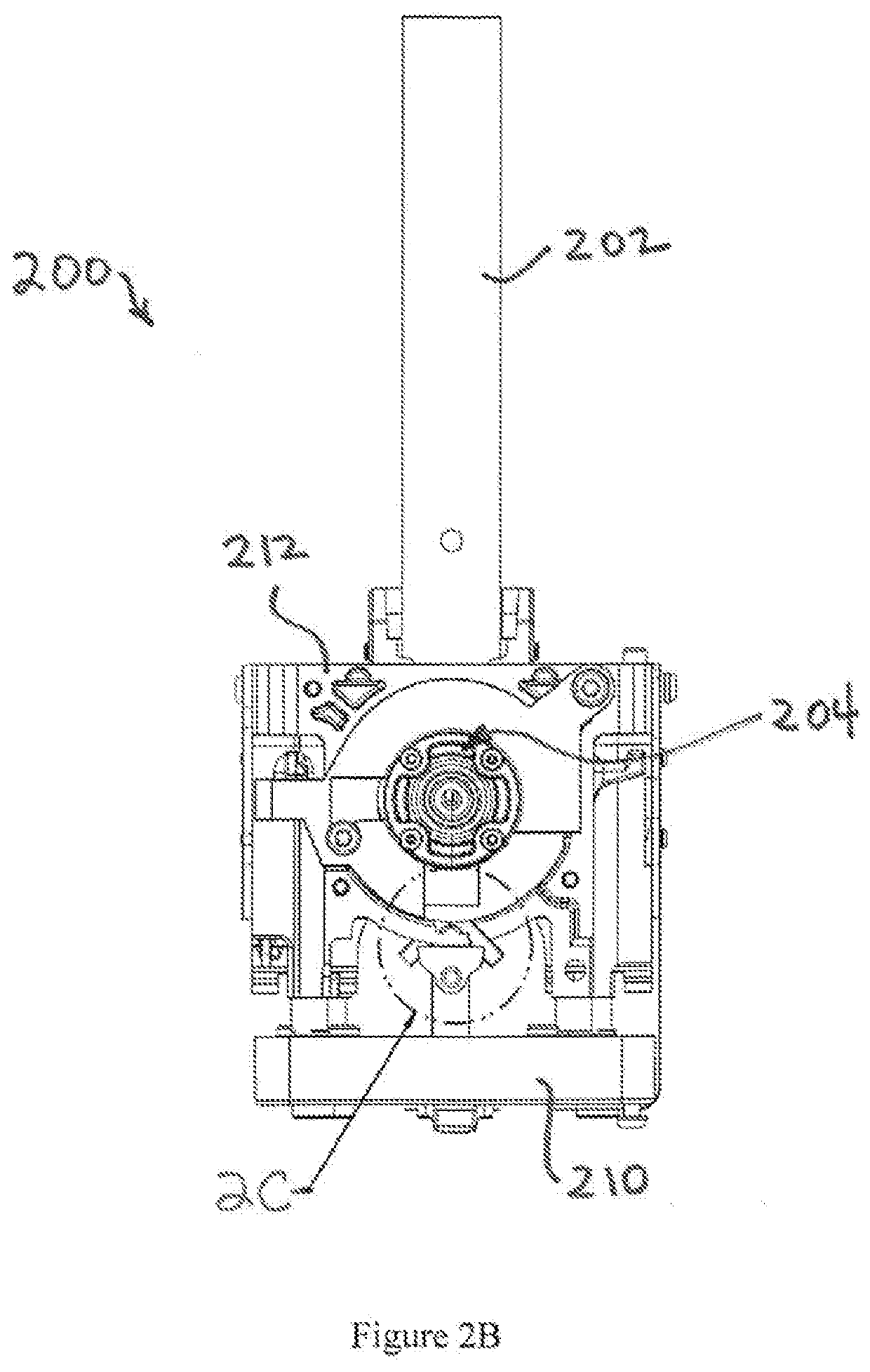
[0025]Referring to FIGS. 2A-C, various views of a joystick assembly 200 are shown. The joystick assembly 200 may be used in construction vehicles, agricultural vehicles, and other applications. The subject technology uses a dual mode sensing joystick assembly 200 to adjust and calibrate the start / stop characteristics of hydraulic flow. In add...


PUM


Abstract

A joystick assembly includes a joystick and pre-load centering springs coupled to the joystick for biasing the joystick to a neutral position. The joystick has a central free-play zone, a transitional zone surrounding the central free-play zone in which the pre-load centering springs begin to act upon the joystick, and a load zone surrounding the transitional zone in which the pre-load centering springs exert a relatively flat spring rate upon the joystick. An angular position sensor system generates a first signal indicative of a travel angle of the joystick. A force sensor system generates a second signal indicative of a force applied to the joystick. A controller receives the first and second signals and sets start / stop points for control by the joystick approximately synchronously with the joystick moving from the transitional zone to the load zone based upon the second signal.

Description

BACKGROUND1. Field of the Technology[0001]The subject disclosure relates to joysticks, and more particularly to improved joysticks for work vehicles and other applications that require enhanced response and performance.2. Background of the Related Art[0002]In recent years, control of construction and agriculture vehicles has transitioned to electro-hydraulic control. Some resistance exists because of controllability deficiencies. In joystick applications, operator feedback and effective control are particularly desirable.[0003]Electro-hydraulic joysticks typically use magnetic sensors to determine motion in two axis. Springs cause physical auto-centering when force is not applied to the joystick. A wide neutral band exists about the spring centered position that does not have the associated tactile feel such as in pilot hydraulic control systems. As a result, it can be difficult for operators to control fine movements and / or work in tight spaces. However, the wide neutral band is re...

Claims


Application Information

Patent Timeline
Patent Type & Authority Applications(United States)
IPC IPC(8): G05G9/047
CPCG05G9/047G05G5/03G05G2009/0474G05G2009/04766B60K20/02B60T7/08G05G2009/04755G05G2009/04762G06F3/0338G06F3/038G05G2009/04725
Inventor O'NEILL, EDMUND C.
Owner SENSATA TECHNOLOGIES INC
Learn More