Cutting sharpness detection device

Active Publication Date: 2020-11-19
CLAAS SELBSTFAHRENDE ERNTEMASCHINEN GMBH
View PDF1 Cites 0 Cited by
  • Summary
  • Abstract
  • Description
  • Claims
  • Application Information

AI Technical Summary

Benefits of technology

[0006]Therefore, it is the object of the invention to avoid the disadvantages of the prior art described above and, in particular, to configure and further develop the kno

Problems solved by technology

Optical sensors have the problem particularly that the cutting edge analysis is made more difficult by the high revolving speeds of the chopping knives, which often leads to poor-qua

Method used


Image

  • Cutting sharpness detection device
  • Cutting sharpness detection device
  • Cutting sharpness detection device

Examples


Example

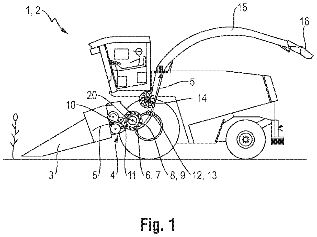
[0029]FIG. 1 schematically shows an agricultural work machine 1 which is constructed as a forage harvester 2 and which receives a harvesting header 3 in the front area thereof. Gathering and pre-compacting rollers 4 which accept the crop flow 5 coming from the harvesting header 3, compress it and transfer it to a chopping device 6 in the rear area is associated with the header 3 in the rear area thereof. In a manner to be described further, the chopping device 6 comprises a chopping drum 7 which is outfitted with chopping knives 8 of a chopping knife arrangement 9. In the feed-in area 10 of the chopping drum 7, the revolving chopping knives 8 are moved past a shear bar 11 by means of which the crop flow 5 to be comminuted is conveyed. In the rear area of the chopping drum 7, the comminuted crop 5 is then transferred either to an after-comminution device 13 constructed as a so-called cracker 12 or directly to an after-acceleration device 14. While the after-comminution device 13 furt...


PUM


Abstract

A detection arrangement for detecting a wear status of a chopping knife arrangement of a chopping device provided for processing a product flow, wherein the chopping device has a revolving chopping drum receiving the chopping knife arrangement and at least one shear bar which cooperates with the chopping knives, with a sensor arrangement which has a magnetic exciter arrangement and a flux conducting device magnetically coupled thereto. The sensor arrangement provides a pole arrangement which forms at least one magnetic pole with a pole surface for conducting magnetic flux, wherein at least a portion of the chopping knife passes the pole arrangement during a rotation of the chopping drum. A voltage induced when a chopping knife arrangement passes the sensor arrangement forms the measured magnetic value, which is used by the evaluation unit to determine the state of wear of the chopping knife arrangement.

Description

CROSS-REFERENCE TO RELATED APPLICATIONS[0001]This application claims priority under 35 USC 119 of German Application No. DE 10 2019 112 968.0, filed on May 16, 2019, German Application No. DE 10 2019 112 973.7, filed on May 16, 2019 and German Application No. DE 10 2019 112 965.6, filed on May 16, 2019, the disclosure of which is herein incorporated by reference.BACKGROUND OF THE INVENTION[0002]The invention is directed to a device for detecting the wear status of a chopping knife arrangement of a chopping device provided for processing a product flow.[0003]A generic sensor arrangement which detects the revolving knives of a chopping drum arrangement by means of inductive sensors and derives a wear status of the chopping knives from the determined magnetic flux is known from DE 10 2017 103 537. Wear is determined from the induced voltage.[0004]In addition, a similar cutting sharpness detection device is known, inter alia, from EP 1 522 214. In this case, optical sensors such as came...

Claims


Application Information

Patent Timeline
IPC IPC(8): G01B7/293A01D41/127A01D43/08
CPCA01D43/085A01D41/127G01B7/293A01F29/22A01D41/1271A01F29/095G01B7/14B60W50/0098B60W50/085B60W2300/158B60W2710/30B02C2018/188B02C2210/02B02C18/186G01B7/023B26D7/12
Inventor HEITMANN, CHRISTOPHNEITEMEIER, DENNISBRUNE, MARKUSHUSTER, JOCHENFISCHER, FRÉDÉRICSTREMLAU, BJOERN
Owner CLAAS SELBSTFAHRENDE ERNTEMASCHINEN GMBH
Why Eureka
Try Eureka