Plugged honeycomb segment, and plugged honeycomb structure

Active Publication Date: 2020-12-10
NGK INSULATORS LTD
View PDF0 Cites 0 Cited by
  • Summary
  • Abstract
  • Description
  • Claims
  • Application Information

AI Technical Summary

Benefits of technology

The present invention provides a plugged honeycomb segment and structure that has low pressure loss, fewer clogged cells, excellent temperature rising properties and isostatic strength. This is achieved through a design that reduces the thickness of the outermost circumferential wall in contact with incomplete cells and increases the bonding strength of the bonding layer when multiple plugged honeycomb segments are bonded. Additionally, the plugged honeycomb structure of the present invention has excellent bonding strength.

Problems solved by technology

Further, as described above, there is a problem that the pressure loss of the plugged honeycomb structure becomes high because the size of the open ends of some cells located at the outermost circumference of each honeycomb segment is reduced.
As described above, there is a problem that, in the honeycomb segment, if the size of the open ends of some cells located at the outermost circumference is reduced, when the catalyst is loaded, the catalyst is easily clogged in the cells whose open end is reduced in size.
However, there is a problem that a uniform suction force is not obtained, and the loading of the catalyst becomes non-uniform.

Method used


Image

  • Plugged honeycomb segment, and plugged honeycomb structure
  • Plugged honeycomb segment, and plugged honeycomb structure
  • Plugged honeycomb segment, and plugged honeycomb structure

Examples


example 1

[0075]As a ceramic raw material, a mixed raw material obtained by mixing silicon carbide (SiC) powder and metallic silicon (Si) powder in a mass ratio of 80:20 was prepared. Hydroxypropylmethyl cellulose as a binder and a water absorbable resin as a pore former were added to this mixed raw material, and water was also added to prepare a forming raw material. The obtained forming raw material was kneaded using a kneader to obtain a kneaded material.

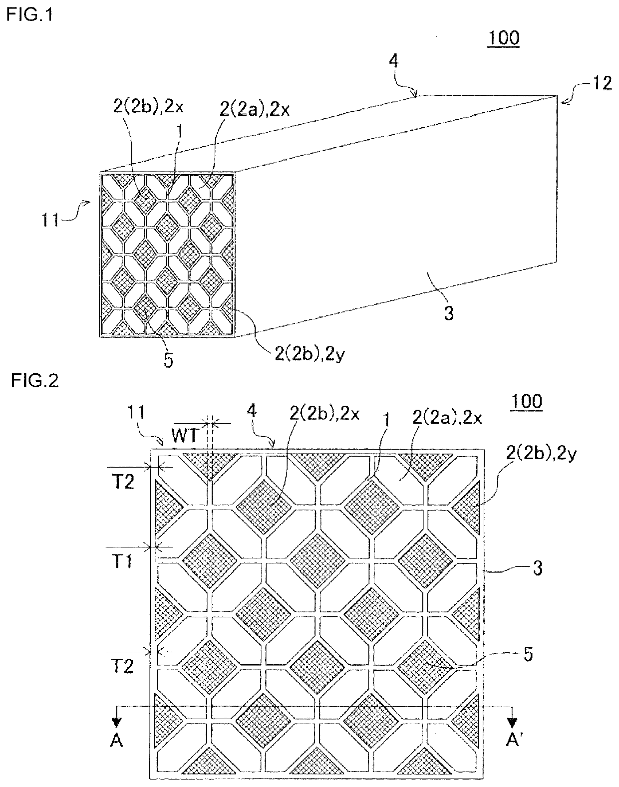
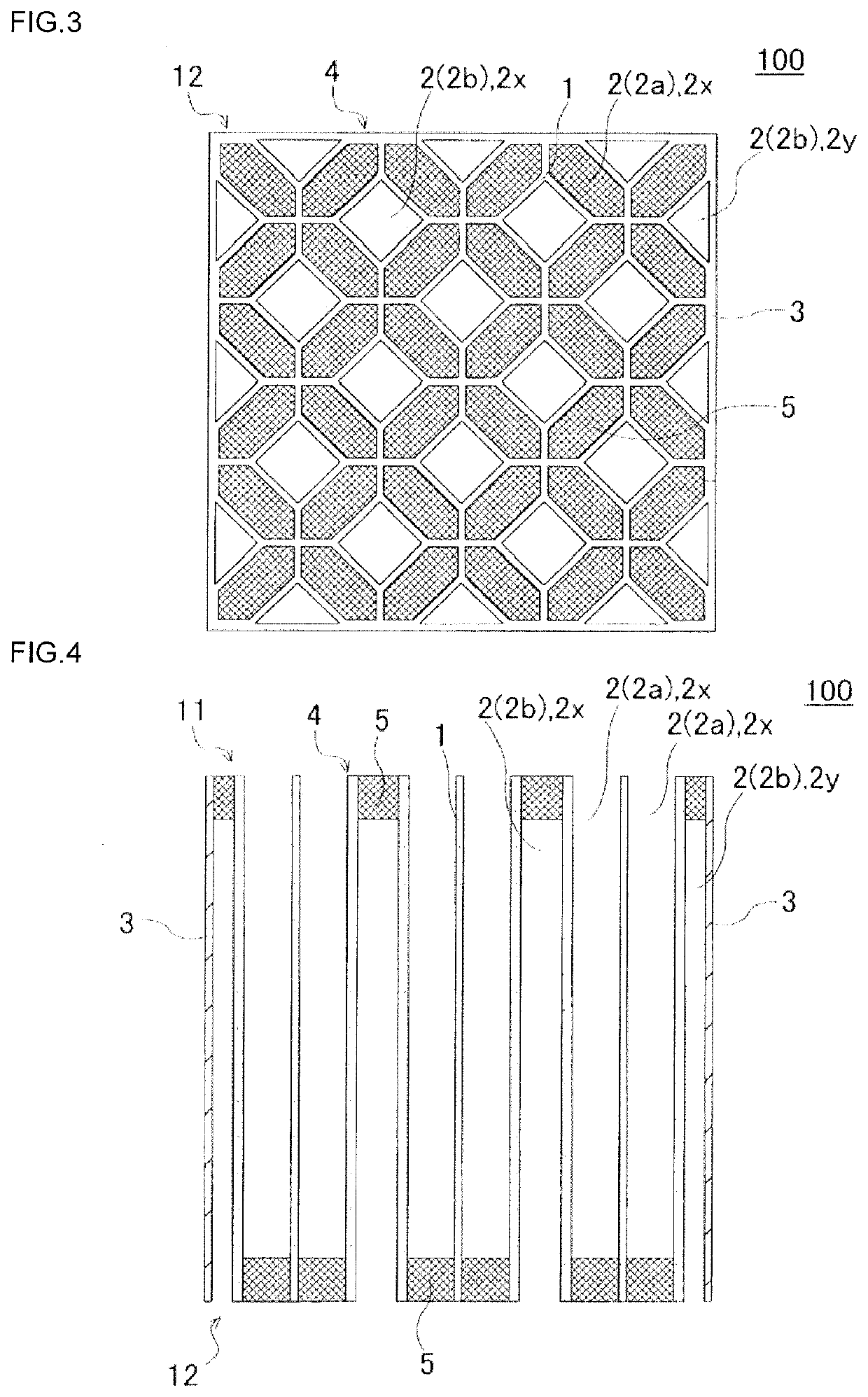
[0076]Next, the obtained kneaded material was molded by using a vacuum extrusion molding machine to manufacture forty-nine honeycomb segments having a quadrangular prism shape and a repeating array pattern similar to that of the plugged honeycomb segment 100 shown in FIG. 2. Note that, the “repeating array pattern similar to that of the plugged honeycomb segment 100 shown in FIG. 2” means a repeating array pattern in which four inflow cells having a hexagonal cross section are arranged so as to surround an outflow cell having a square cros...

examples 2 to 8

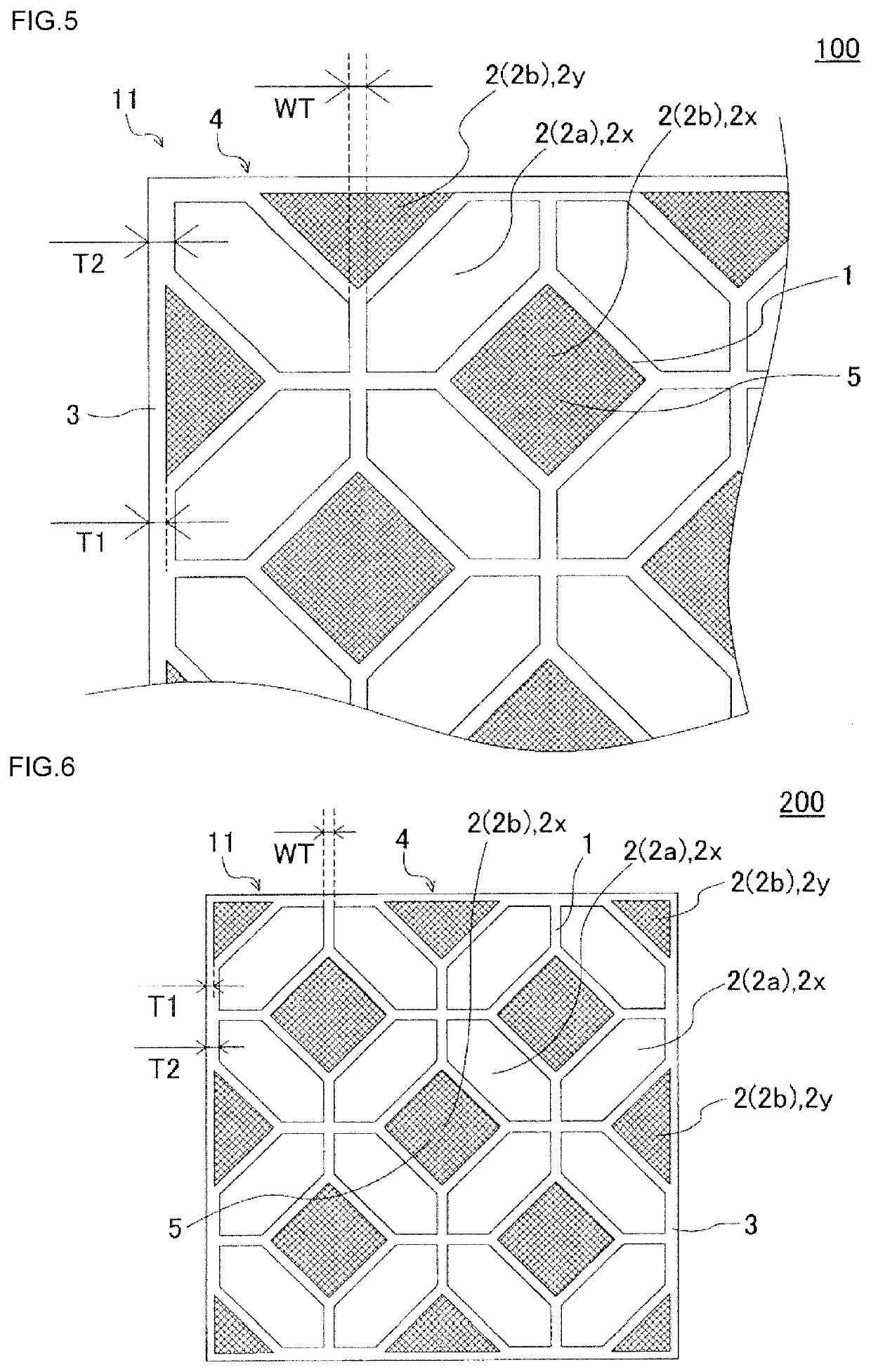
[0115]Plugged honeycomb structures were manufactured in the same method as in Example 1 except that the structure of the plugged honeycomb segment was changed as shown in Table 1. Note that, in the plugged honeycomb structure of Example 8, an outernost circumferential wall having a thickness of T2 (mm) was present at a position forming a corner on an end face of a honeycomb segment.


PUM

PropertyMeasurementUnit
Lengthaaaaaaaaaa
Fractionaaaaaaaaaa
Thicknessaaaaaaaaaa

Abstract

A plugged honeycomb segment includes a honeycomb segment having a quadrangular prism shape which includes porous partition walls arranged to surround a plurality of cells and an outermost circumferential wall, and a plugging portion, wherein a porosity of the partition walls is 30 to 70%, in a cross section orthogonal to the cell extending direction, an inflow cell surrounded by the partition walls is a hexagon, and an outflow cell is a square, one outflow cell is surrounded by four inflow cells, the cell located at the outermost circumference includes a complete cell and an incomplete cell, and a thickness of the outermost circumferential wall in contact with the incomplete cell (T1), a thickness of the outermost circumferential wall in contact with the complete cell (T2), and a thickness of the partition walls (WT), satisfy 0.200 mm<T1<T2−(½×WT) and T2≤0.700 mm.

Description

BACKGROUND OF THE INVENTIONField of the Invention[0001]The present invention relates to a plugged honeycomb segment and a plugged honeycomb structure. More specifically, the present invention relates to a plugged honeycomb segment and a plugged honeycomb structure in which the pressure loss is low, cells are less likely to be clogged when a catalyst is loaded, and the temperature rising property and the isostatic strength (for example, tightening resistance) are excellent.Description of the Related Art[0002]In recent years, reduction of fuel consumption of automobiles has been demanded from the viewpoint of impact on the global environment and resource saving. Therefore, internal combustion engines with high thermal efficiency such as a direct injection gasoline engine or a diesel engine tend to be used as a power source for automobiles.[0003]On the other hand, in these internal combustion engines, the generation of burnt residue when fuel is combusted is a problem. From the perspec...

Claims


Application Information

Patent Timeline
IPC IPC(8): B01J35/04C04B38/00B01D53/88
CPCC04B38/0009B01J35/04B01D2255/9202B01D53/885B01D2255/9205B01D2255/9155C04B2111/00793B01D46/2478B01D46/249B01D46/24491B01D46/2429B01D46/2492B01D46/247B01D46/2498B01D46/2482B01D46/2474B01J35/56C04B35/565C04B38/0074
Inventor SASAKI, YUJI
Owner NGK INSULATORS LTD
Why Eureka
Try Eureka