

Depth filter
- Summary
- Abstract
- Description
- Claims
- Application Information
AI Technical Summary
Benefits of technology
Problems solved by technology
Method used
Image

Examples
example 1
(Material)
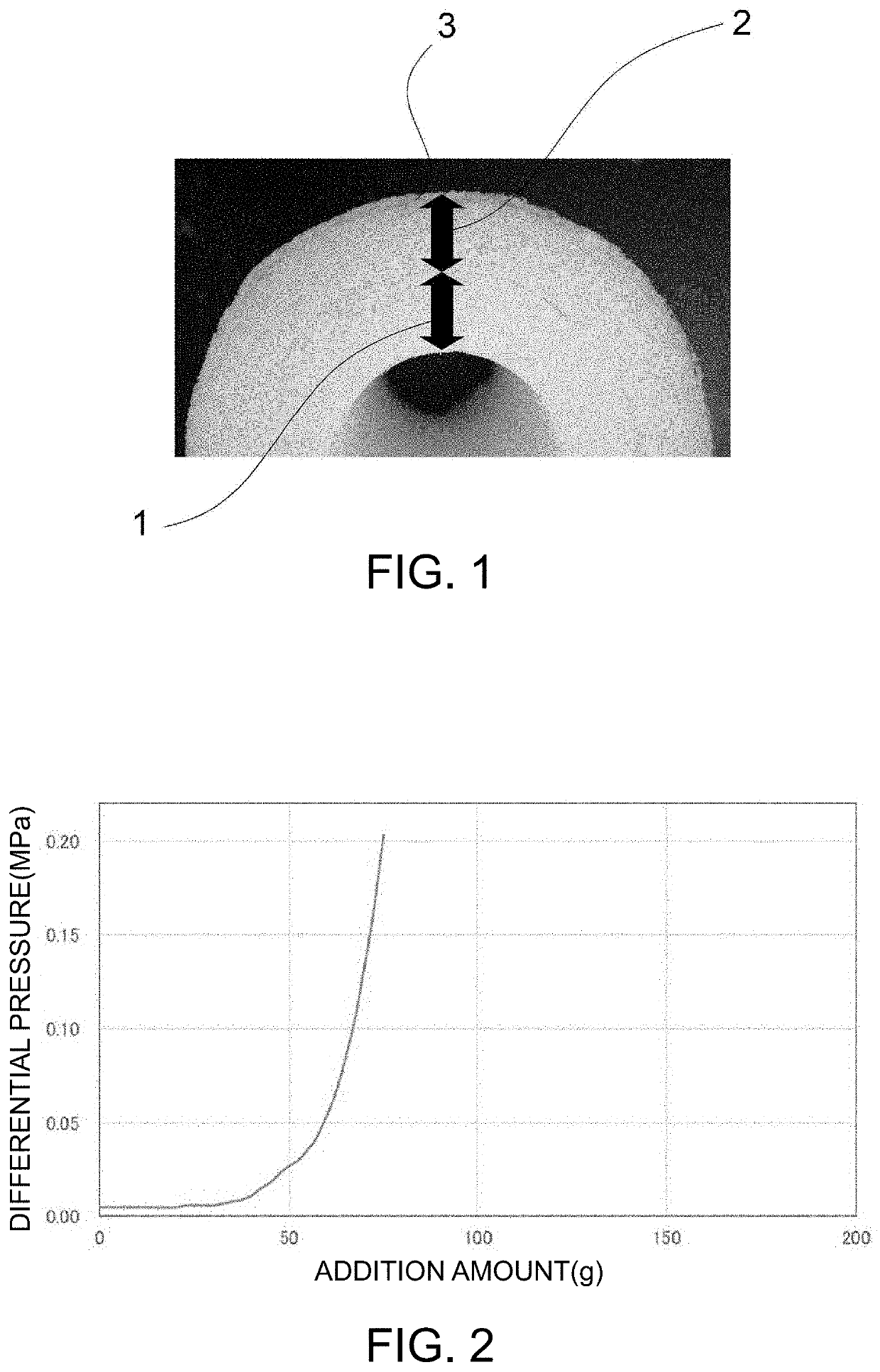
[0076]Nonwoven cloth for skin layer and substrate layer: A melt-blown nonwoven cloth containing crystalline propylene (melting point 165° C.) as a main component, which has a basis weight of 47 g / m2 and an average fiber diameter of 343 μm, was used.
[0077]Nonwoven cloth for filtration layer: A through-air nonwoven cloth formed of eccentric sheath-core type composite fibers (average fiber diameter 31 μm) of crystalline polypropylene (melting point 165° C.: core) / high density polyethylene (melting point 135° C.: sheath), which has a basis weight of 30 g / m2 and an average pore diameter of 46 μm, was used. The average pore diameter is a value obtained by measuring four through-air nonwoven cloths stacked.
[0078]Net: A net formed of polypropylene monofilaments (average fiber diameter 250 μm), which has a mesh size of 2.0 mm, was used.
(Manufacturing Method of Filter)
[0079]The core (the iron rod) was preheated to 150° C., the heating at 150° C. was continued, and in the meantime, t...
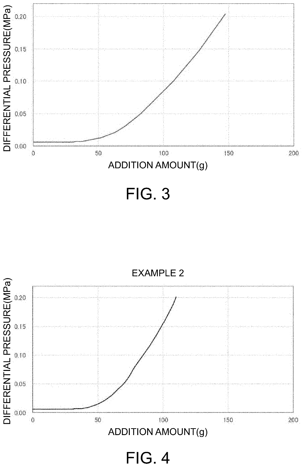
example 2
(Material)
[0080]Nonwoven cloth for skin layer and substrate layer: A melt-blown nonwoven cloth containing crystalline propylene (melting point 165° C.) as a main component, which has a basis weight of 47 g / m2 and an average fiber diameter of 182 μm, was used.
[0081]Nonwoven cloth for filtration layer: A through-air nonwoven cloth formed of eccentric sheath-core type composite fibers (average fiber diameter 31 μm) of crystalline polypropylene (melting point 165° C.: core) / high density polyethylene (melting point 135° C.: sheath), which has a basis weight of 30 g / m2 and an average pore diameter of 46 μm, was used. The average pore diameter is a value obtained by measuring four through-air nonwoven cloths stacked.
[0082]Net: A net formed of polypropylene monofilaments (average fiber diameter 250 μm), which has a mesh size of 2.0 mm, was used.
(Manufacturing method of filter)
[0083]The core (the iron rod) was preheated to 150° C., the heating at 150° C. was continued, and in the meantime, t...
PUM
| Property | Measurement | Unit |
|---|---|---|
| Diameter | aaaaa | aaaaa |
| Diameter | aaaaa | aaaaa |
| Diameter | aaaaa | aaaaa |
Abstract
Description
Claims
Application Information