
Urea production process and plant with heat integration in low pressure recovery section

a production process and low pressure recovery technology, applied in the direction of separation processes, pressure vessels for chemical processes, organic chemistry, etc., can solve the problems of difficult construction of horizontal pool condensers, high corrosion, heat exchanger sections

Active Publication Date: 2020-12-10
STAMICARBON BV
View PDF0 Cites 1 Cited by
  • Summary
  • Abstract
  • Description
  • Claims
  • Application Information

AI Technical Summary

Benefits of technology

The present invention offers an efficient and low-pressure urea production process and plant design. The technical effects include reduced energy consumption and simplified high-pressure section design.

Problems solved by technology

A disadvantage of US 2015 / 0119603 is that the first heat exchanger section, e.g. a U-shaped tube bundle, is contact with process medium on both sides.
The process medium contains ammonium carbamate and is highly corrosive at the temperatures associated with high pressure and medium pressure operation.
This makes it difficult to construct the horizontal pool condenser, in particular the tube-to-tubesheet connection, taking into account that the corrosive fluid in the tubes passes through the bore holes in the tubesheet, which tubesheet consist of carbon steel sandwiched with two corrosion-resistant liners.

Method used


Image

  • Urea production process and plant with heat integration in low pressure recovery section
  • Urea production process and plant with heat integration in low pressure recovery section

Examples


example 1

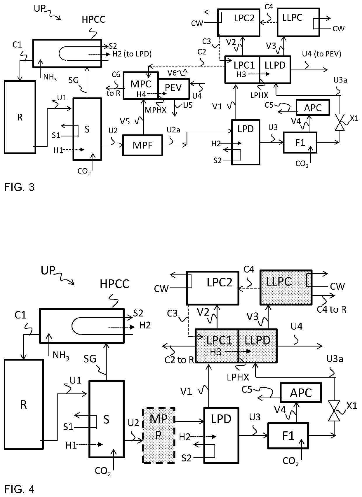
[0113]An example process is carried out with the process scheme of FIG. 3. The HP stripper operates with an example stripping efficiency (alfa) of 0.63 and the stripper has at the outlet the stripped urea solution U1 at 170-180° C. and 140-145 bar (HP) (all pressure are absolute pressure), which is adiabatically flashed in MPF to give a flashed urea solution U2a at 20-30 bar (MP) and 140-150° C. Stream U2a is supplied to the decomposer LPD for decomposition of carbamate which has a rectifying column and gives stream U3 at 5-8 bar (LP) and 130-140° C., which is flashed in flash vessel F1 to 1-1.3 bar and expanded in valve X1 to 0.3-0.5 bar absolute (LLP) at 60-70° C. at the inlet of LLPD. Optionally some fresh CO2 is added to flash vessel F1 for N / C correction. Vapor V3 from LLPD is 70-85° C. and 0.3-0.5 bar. Urea solution U4 at the outlet of LLPD and inlet of PEV is 0.3-0.5 bar and 75-90° C. and is heated to give urea solution U5 at 125-135° C. and 0.3-0.5 bar. Vapor V5 from MPF is ...


PUM

PropertyMeasurementUnit
Efficiencyaaaaaaaaaa
Pressureaaaaaaaaaa

Abstract

The invention pertains to a urea production process using a high pressure stripper and a low pressure decomposer connected to a low pressure carbamate condenser which is in heat exchanging contact through a wall with a sub-atmospheric decomposer wherein urea solution obtained from the low pressure decomposer is processed.

Description

INTRODUCTION[0001]The invention pertains to a urea production process and plant of the stripping type, and to a method of modifying an existing urea plant.[0002]Urea processes with a high pressure stripper and without a high pressure stripper are known. In a urea process without a high pressure stripper, heat supplied to the urea synthesis solution is typically used only once; therefore, this type of process can be referred to as an N=1 process. In urea processes using high pressure stripping, heat is imported in the first heater (the stripper), recovered in the high pressure carbamate condenser, and re-used in low pressure heaters. The heat supplied is effectively used twice; thus the term “N=2 process” is used. The average energy consumption of the stripping process is 0.8-1.0 ton of steam per ton of urea.[0003]In an example typical urea process of the Stamicarbon CO2 stripping type, gas from the low pressure decomposer is passed through a rectifying column (for counter-current co...

Claims


Application Information

Patent Timeline
IPC IPC(8): C07C273/14C07C273/04B01J3/04B01D3/00B01D3/06B01D5/00
CPCB01J3/04C07C273/14B01D5/006C07C273/04B01D3/009B01D5/0003B01D3/06
Inventor PATIL, RAHULBUITINK, FREDERICUS HENRICUS MARIA
Owner STAMICARBON BV
Learn More