Optical module

a technology of optical modules and optical elements, applied in the direction of optical elements, wavelength-division multiplex systems, instruments, etc., can solve the problems of delayed commercialization and achieve the effect of ensuring the thermal stability of dc light sources and high light source performan

Active Publication Date: 2020-12-10
ELECTRONICS & TELECOMM RES INST
View PDF0 Cites 2 Cited by
  • Summary
  • Abstract
  • Description
  • Claims
  • Application Information

AI Technical Summary

Benefits of technology

[0004]An aspect provides a method of securing thermal stability of DC light sources and high level of light source performance (optical output intensity, relative intensity noise, and line width...

Problems solved by technology

Although it was predicted for years that small-size, low-price, and high-speed optical transceivers become commercially available through silicon-based photonics technology, the commercialization has...

Method used


Image

  • Optical module
  • Optical module
  • Optical module

Examples


Embodiment Construction

[0040]Hereinafter, example embodiments will be described in detail with reference to the accompanying drawings.

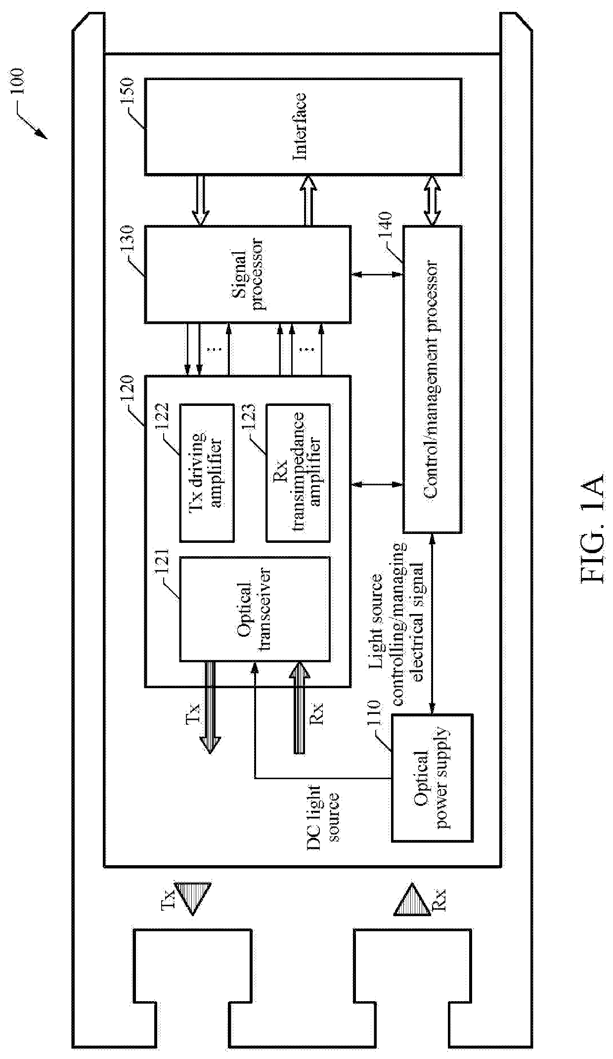
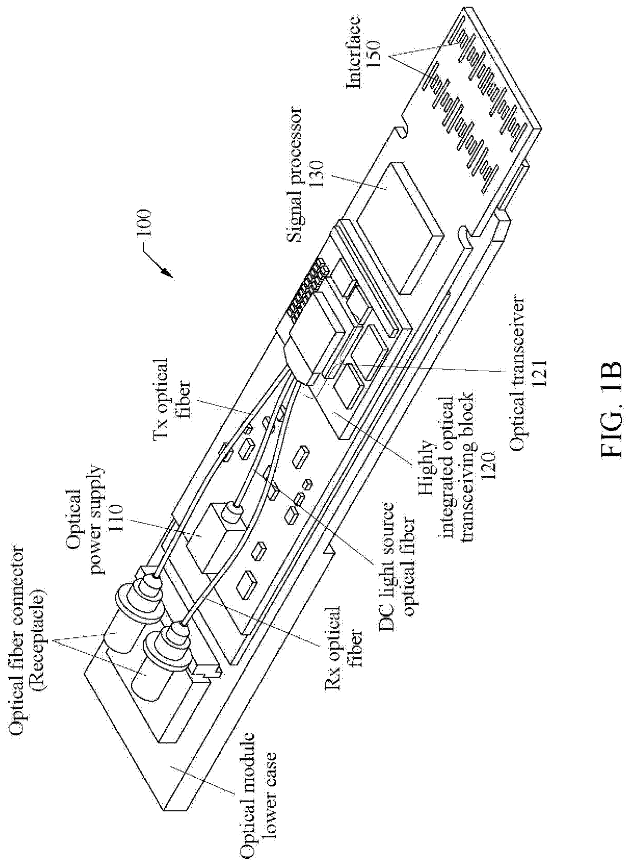
[0041]FIGS. 1A and 1B illustrate a structure of an optical module according to a first example embodiment.

[0042]In detail, FIG. 1A is a plan view of an optical module 100 according to the first example embodiment, and FIG. 1B is a perspective view of the optical module 100. Referring to FIGS. 1A and 1B, the optical module 100 may include an optical power supply 110, a highly integrated optical transceiving block 120, a signal processor 130, a control / management processor 140, and an interface 150. In this example, the highly integrated optical transceiving block 120 may include an optical transceiver 121 including a silica optical waveguide-based multiplexing block and a silicon photonics-based optical device block, a transmission driving amplifier (driver IC) 122, that is, an optical transmission and reception amplifier which is an electronic device that amplifies optical ...


PUM


Abstract

An optical module includes an interface electrically connected to an external device to receive a data signal to be transmitted, a signal processor configured to perform serialization and signal modulation on the received data signal, an optical transceiver configured to generate an optical transmission signal by receiving a direct current (DC) light source, in which a plurality of light sources having different wavelengths are multiplexed, from an optical power supply and performing optical modulation thereon through the serialized and modulated data signal, and an optical fiber connector configured to output the generated optical transmission signal to the external device and receive an optical reception signal from the external device.

Description

BACKGROUND1. Field of the Invention[0001]One or more example embodiments relate to a structure of an optical module that functions as an optical transmission and reception interface in a data center network.2. Description of Related Art[0002]An optical module is a device that modulates an electrical signal into an optical signal, or receives an optical signal and converts the optical signal into an electrical signal. The optical module performs optical connection for high-speed signal transmission in a data center network. With an increase in the amount of data to be transmitted through an optical module, there is a demand for high-speed, small-size, and low-price optical transmitter and optical receiver which are the main blocks.[0003]Such an optical transceiver may be implemented by integrating an optical device and an electronic device in a limited space. Silicon photonics capable of manufacturing large amounts of optical transceivers through a silicon wafer process is a technolo...

Claims


Application Information

Patent Timeline
IPC IPC(8): G02B6/12G02B6/293H04B10/40H04B10/25H04B10/27H04B10/60G02B6/287
CPCG02B6/2938H04B10/60H04B10/27G02B6/287H04B10/25G02B6/12007H04B10/40H04J14/02H04B10/66G02B6/4246G02B6/4266G02B6/4225G02B6/4292G02B6/12019G02B6/421
Inventor KANG, SAE-KYOUNGSONG, JONGTAEHUH, JOON YOUNG
Owner ELECTRONICS & TELECOMM RES INST
Why Eureka
Try Eureka