Efficient multi-zone multi-velocity HVAC control method and apparatus

a multi-zone, hvac control technology, applied in lighting and heating apparatus, heating types, applications, etc., can solve the problems of increasing air pressure in the system, reducing user comfort and energy efficiency, and reducing the effect of damper operation on damper operation or elimination, and reducing the noise of higher pressure air flow, the effect of reducing the noise of the airflow

Inactive Publication Date: 2020-12-17
PULICE LUIGI
View PDF0 Cites 3 Cited by
  • Summary
  • Abstract
  • Description
  • Claims
  • Application Information

AI Technical Summary

Benefits of technology

[0003]The present invention provides a multiple zone heating and cooling control system and method wherein undesirable conditioning due to damper operation is reduced or eliminated and noise due to higher pressure air flow is significantly attenuated. In particular, the present invention provides a means to monitor changes in pressure due to damper operation and air circulator fan speed and to reactively adjust air circulator fan speed in order to maintain a desirable static pressure. Unlike prior art embodiments and due to its ability to maintain a desirable static pressure, the present invention permits the full closure of zone dampers as required by the operation of the multiple zone HVAC system. Thereby, this invention is able to provide significantly greater user comfort and energy efficiency, particularly in higher pressure high and medium velocity HVAC systems, permitting an increase in the number of zones while delivering performance generally free of the deficiencies of the prior art.

Problems solved by technology

The system is unable to fully close dampers due to the need to retain the ability to vent excess air in the system.
As a result, undesirable conditioning may be delivered to zones which do not demand it.
Due to the reduction in the capacity of the duct system to process excess air flow upon the partial closure of one or more dampers, the air pressure in the system increases, often dramatically.
The increased pressure in the duct system subsequently increases the rate of air flow through the remaining open dampers causing significantly undesirable conditioning performance and noise at registers.
The number of zones in such systems is limited due to the amplification of the deficiencies with the addition of each zone.
Further, there is a significant drop in the overall energy efficiency of the multiple zone heating and cooling system when undesirable conditioning and noise are present.

Method used


Image

  • Efficient multi-zone multi-velocity HVAC control method and apparatus
  • Efficient multi-zone multi-velocity HVAC control method and apparatus
  • Efficient multi-zone multi-velocity HVAC control method and apparatus

Examples


Embodiment Construction

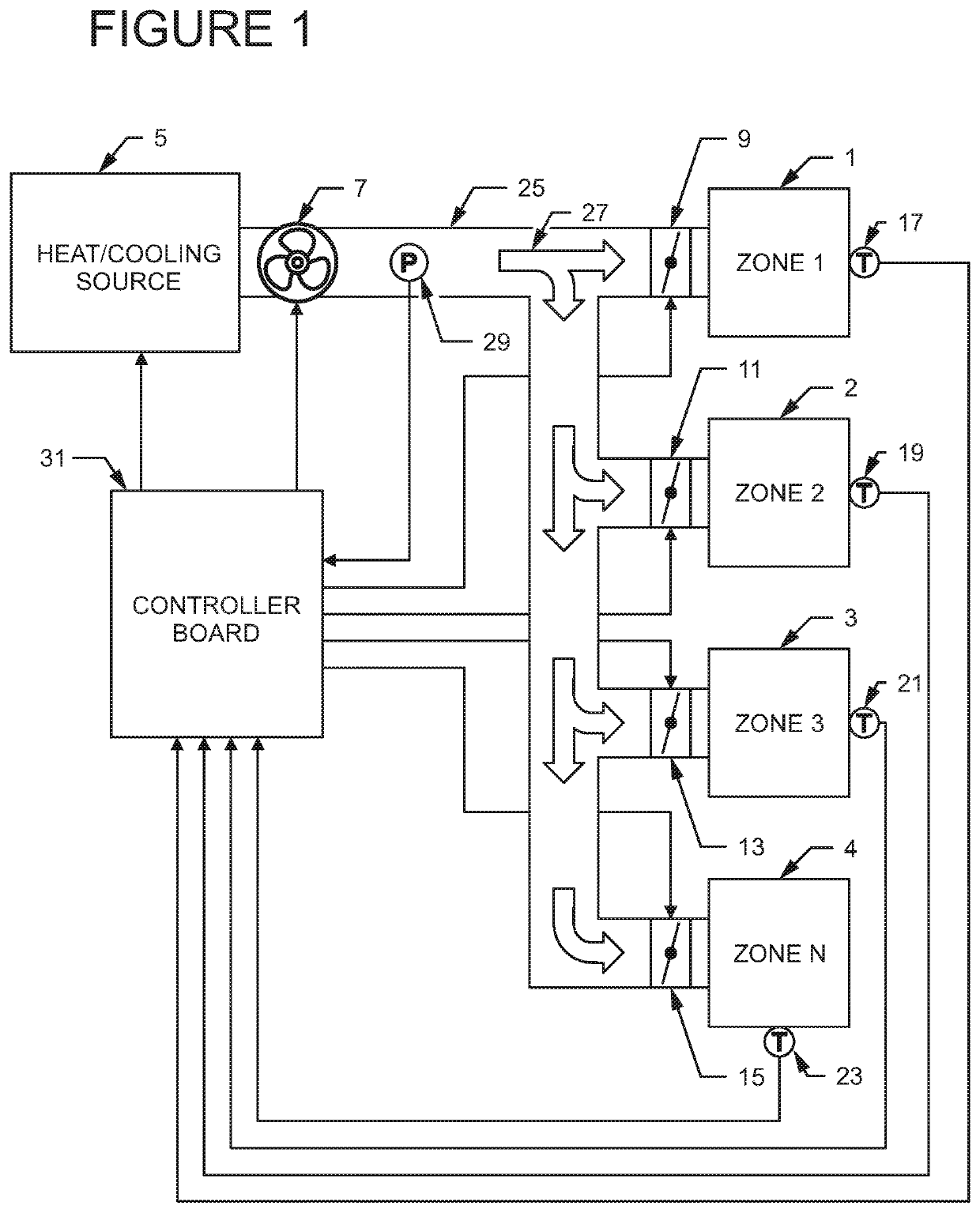
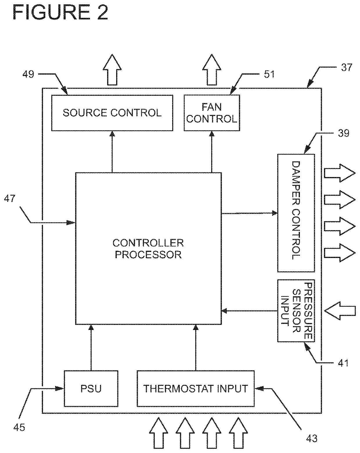
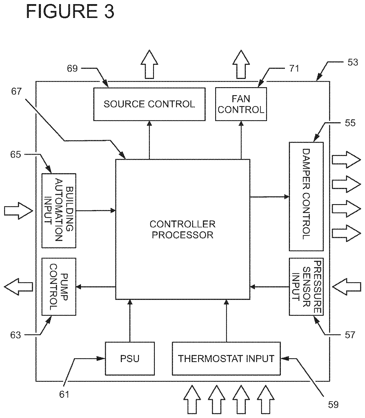
[0007]In order to better understand the embodiment of the present invention, an embodiment of an efficient multiple zone and multiple velocity HVAC control method and apparatus will be described with reference to FIGS. 1, 2, and 3. An embodiment of an implementation of an efficient multiple zone and multiple velocity HVAC control apparatus within an HVAC system is provided as in FIG. 1 comprised of a heating and / or cooling source 5, an air circulator fan with variable speed motor 7, a duct network 25 to direct airflow as illustrated by arrow 27, a pressure sensor 29, motorized dampers 9, 11, 13 and 15 servicing zones 1, 2, 3, and 4 respectively, thermostats 17, 19, 21, and 23, and controller board 31. Operation of said HVAC system is initiated by input from thermostats 17, 19, 21, and 23 providing real-time temperature and user desired temperature input to the controller board 31. Further data such as the static pressure in the duct network 25 is provided to the controller board 31 ...


PUM


Abstract

The present invention provides heating and cooling conditioning control in a multiple zone HVAC system to achieve enhanced user comfort and energy efficiency. In particular, the present invention provides a multiple zone HVAC control apparatus that senses and responds to changes in duct air pressure in order to prevent undesirable zone conditioning, energy loss, and register noise. The present invention offers particular benefit in high and medium velocity HVAC environments which typically suffer from pronounced deficiencies when zone demands diverge. Due to its ability to respond to changes in duct pressure, the present invention permits the conditioning of an increased number of zones without degradation in performance or user comfort. Additionally, the present invention provides a means to control elements within a multiple zone HVAC system including but not limited to heating and cooling sources, air circulator fans, zone dampers, and circulating pumps to achieve desired zone conditioning.

Description

BACKGROUND OF THE INVENTION1. Field of the Invention[0001]The present invention generally relates to control systems used to regulate heating and cooling in HVAC systems. Specifically, the present invention relates to methods and apparatus employed to control the temperature and flow of forced air through duct systems for the regulation of indoor climate. The application of the present invention for the regulation of indoor temperature is appropriate where a forced air heating or cooling source is available to provide air flow through a duct system. This invention finds particular application where the forced air duct system is divided into zones each requiring discrete comfort conditioning, employs high or medium velocity small diameter ducts, and where increased efficiency and reduced noise in the delivery of said conditioning is desirable.2. Description of the Prior Art[0002]Prior art embodiments of HVAC control systems are generally capable of switching heating and cooling sourc...

Claims


Application Information

Patent Timeline
Patent Type & Authority Applications(United States)
IPC IPC(8): F24F3/044F24F11/62F24F11/46F24F13/10
CPCF24F2110/30F24F2120/10F24F13/10F24F3/044F24F11/46F24F11/62F24F3/0442F24F11/745F24F11/77F24F2110/40Y02B30/70
Inventor PULICE, LUIGI
Owner PULICE LUIGI
Why Eureka
Try Eureka