Supercharge Your Innovation With Domain-Expert AI Agents!

Phase detection circuit, clock generation circuit and semiconductor apparatus using the phase detection circuit

a phase detection circuit and clock generation technology, applied in the direction of pulse automatic control, multiple input and output pulse circuits, generating/distributing signals, etc., can solve the problem that the phase difference of the plurality of internal clock signals might not be constan

Active Publication Date: 2020-12-24
SK HYNIX INC
View PDF0 Cites 1 Cited by
  • Summary
  • Abstract
  • Description
  • Claims
  • Application Information

AI Technical Summary

Benefits of technology

The patent describes a circuit that detects the phase relationship between two clock signals. It includes an edge trigger circuit, a strobe generation circuit, and a phase detector. The edge trigger circuit generates falling and rising clock signals based on a reference clock signal and a target clock signal. The strobe generation circuit generates a falling strobe signal with a pulse width and a rising strobe signal with a pulse width based on the falling clock signal. The phase detector generates a phase detection signal by comparing the positive and negative output signals. This circuit can accurately detect the phase relationship between clock signals, which is important in many applications such as communication devices.

Problems solved by technology

However, the plurality of internal clock signals are generated through different clock paths from one another and therefore the plurality of internal clock signals might not have constant phase differences due to skews of the clock paths.

Method used


Image

  • Phase detection circuit, clock generation circuit and semiconductor apparatus using the phase detection circuit
  • Phase detection circuit, clock generation circuit and semiconductor apparatus using the phase detection circuit
  • Phase detection circuit, clock generation circuit and semiconductor apparatus using the phase detection circuit

Examples


Embodiment Construction

[0018]Hereinafter, a semiconductor apparatus according to various embodiments will be described below with reference to the accompanying drawings through various embodiments.

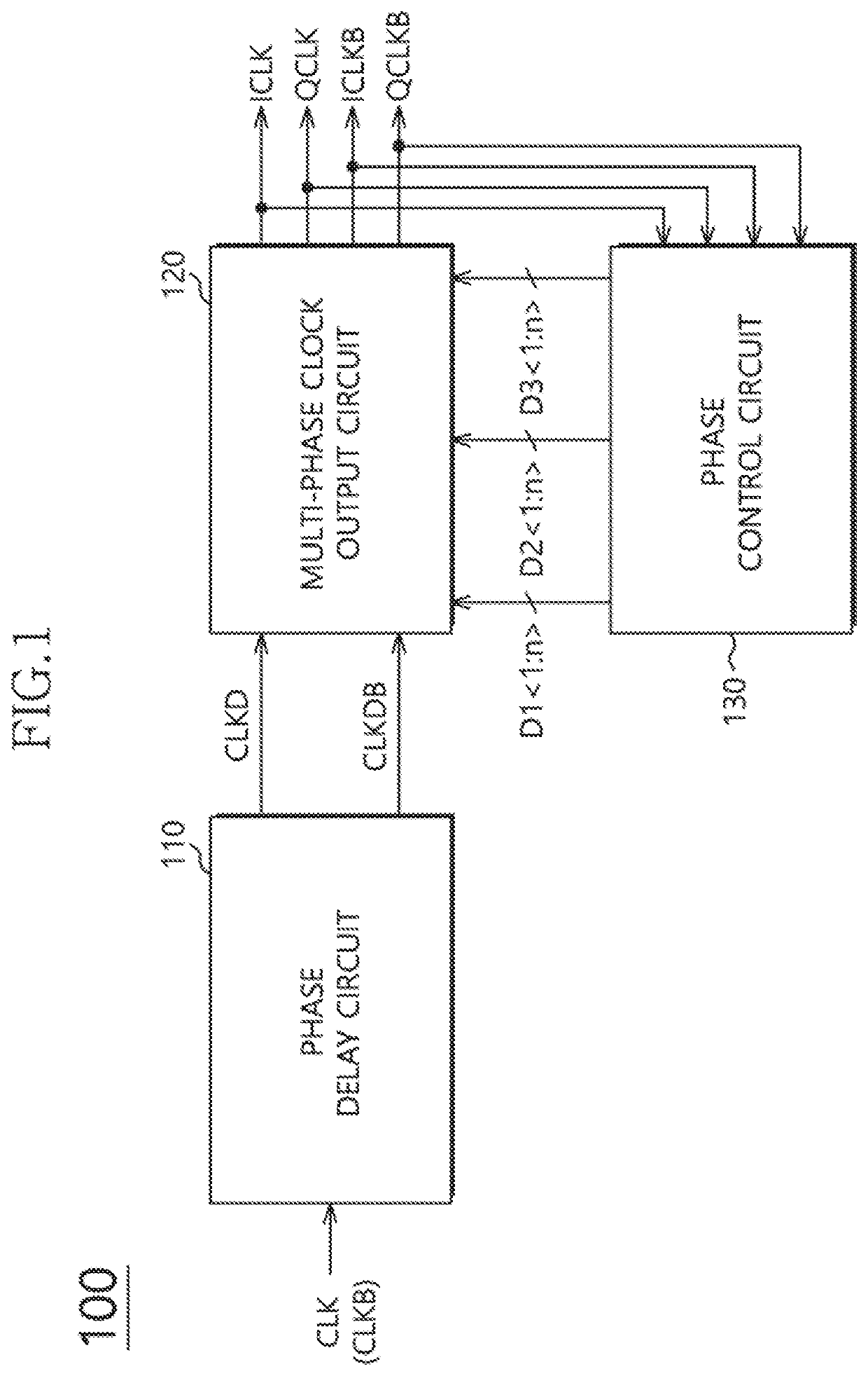
[0019]FIG. 1 is a schematic diagram illustrating a configuration of a clock generation circuit 100 in accordance with an embodiment. Referring to FIG. 1, the clock generation circuit 100 may generate, from a clock signal CLK, a plurality of internal clock signals having different phases from one another. The clock generation circuit 100 may detect the phases of the plurality of internal clock signals. The clock generation circuit 100 may detect the phases of the plurality of internal clock signals by generating a detection clock signal and a strobe signal based on the plurality of internal clock signals; and by detecting a duty ratio of the detection clock signal. The clock generation circuit 100 may adjust the phases of the plurality of internal clock signals according to a result of the phase detection.

[0020]T...


PUM


Abstract

A phase detection circuit may include an edge trigger circuit, a strobe generation circuit and a phase detector. The edge trigger circuit generates a falling clock signal and a rising clock signal based on a reference clock signal and a target clock signal. The strobe generation circuit generates a falling strobe signal and a rising strobe signal having pulse widths varying based on a phase relationship between the reference clock signal and the target clock signal. The phase detector generates a phase detection signal based on the falling clock signal, the rising clock signal, the falling strobe signal and the rising strobe signal.

Description

CROSS-REFERENCES TO RELATED APPLICATION[0001]The present application claims priority under 35 U.S.C. § 119(a) to Korean application number 10-2019-0074042, filed on Jun. 21, 2019, in the Korean Intellectual Property Office, which is incorporated herein by reference in its entirety.BACKGROUND1. Technical Field[0002]Various embodiments generally relate to an integrated circuit technology and, more particularly, to a clock generation circuit is and a semiconductor apparatus.2. Related Art[0003]An electronic device includes a lot of electronic elements, and a computer system includes lots of semiconductor apparatuses each comprising a semiconductor. Semiconductor apparatuses configuring a computer system may communicate with each other by receiving and transmitting data and a system clock signal such as an external clock signal. The semiconductor apparatuses may operate in synchronization with a clock signal. In order to become in synchronization with an external apparatus or to secure ...

Claims


Application Information

Patent Timeline
IPC IPC(8): G06F1/10G06F1/06H03K5/24G06F1/12
CPCG06F1/12G06F1/06H03K5/24G06F1/10H03L7/085H03L7/18G11C7/222H03K5/1565H03K5/1534H03K5/135G11C7/22G11C11/4076
Inventor PARK, GYU TAE
Owner SK HYNIX INC
Features
  • R&D
  • Intellectual Property
  • Life Sciences
  • Materials
  • Tech Scout
  • Unparalleled Data Quality
  • Higher Quality Content
  • 60% Fewer Hallucinations
Learn More