Systems and methods for measuring structural element deflections

a technology of structural elements and systems, applied in the direction of three-component magnetometers, measurement instrument magnets, instruments, etc., can solve the problems of lack of infrastructure facilities capable of providing the requisite data, lack of on-site data processing capabilities, and cost of conducting calibration and empirical data gathering at the structur

Pending Publication Date: 2020-12-31
MACHINESENSE LLC
View PDF10 Cites 0 Cited by
  • Summary
  • Abstract
  • Description
  • Claims
  • Application Information

AI Technical Summary

Benefits of technology

[0052]Furthermore, by this disclosure, there is no intention to be limited by any express or implied theory presented in the preceding materials, including but not limited to the summary of the invention or the description of the prior art, or in the following description of the invention. It is to be understood that the specific implementations, devices, processes, aspects, and the like illustrate

Problems solved by technology

One of the challenges in structural health monitoring, however, is in performing the requisite analyses, and generating actionable information in real-time.
This challenge exists due, in general, to the absence of infrastructure facilities capable of providing the requisite data analyses; the costs of conducting calibration and empirical data gathering on-site at the structure; and the lack of on-site data-processing capabilities.
Such methods, however, can be costly and have limitations.
For example, the results of the total station method can be affected by temperature changes and humidity.
Also, most of these methods are limited to determining single-axis axis deflection of a structural

Method used


Image

  • Systems and methods for measuring structural element deflections
  • Systems and methods for measuring structural element deflections
  • Systems and methods for measuring structural element deflections

Examples


Embodiment Construction

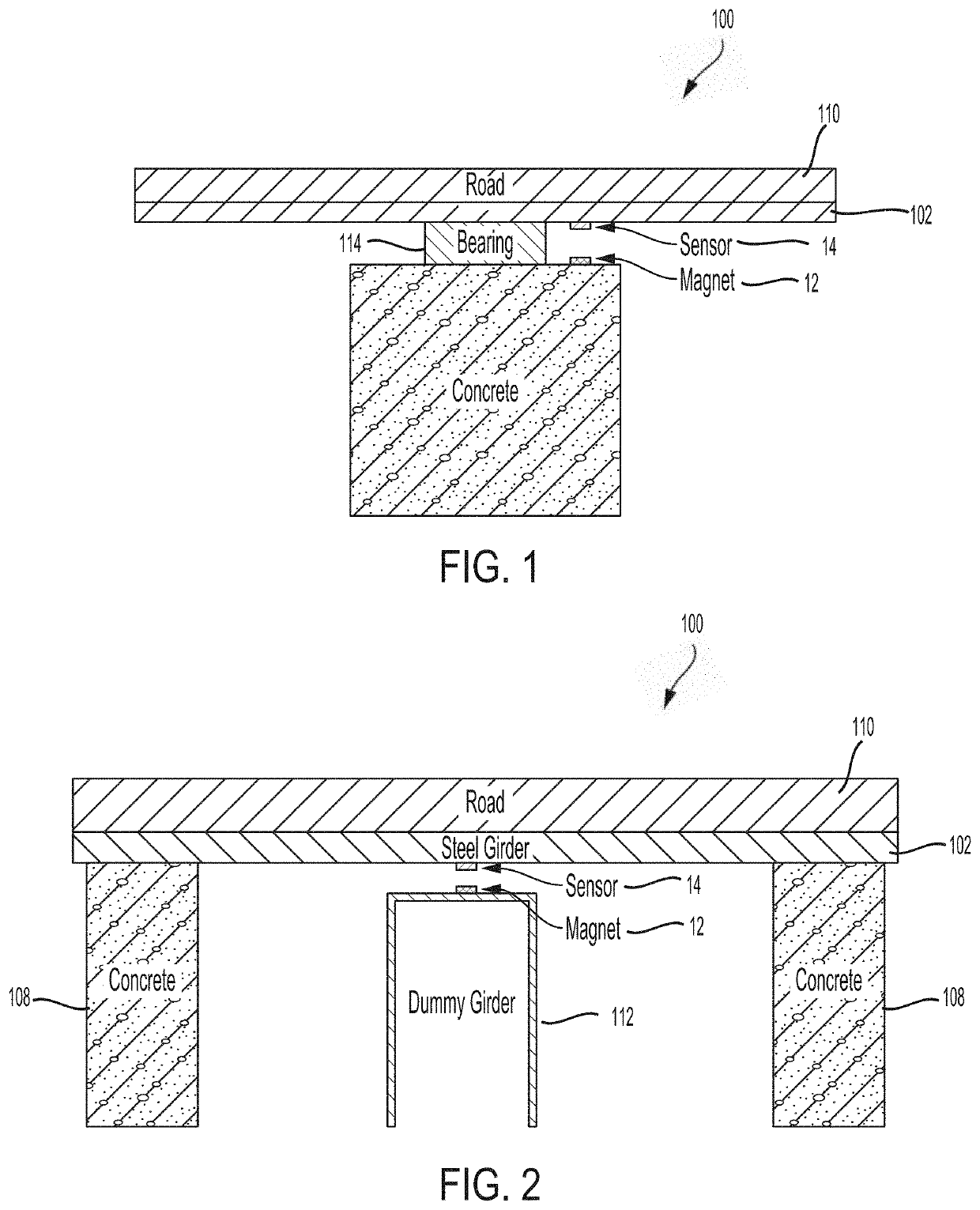
[0072]The inventive concepts are described with reference to the attached figures. The figures are not drawn to scale but do illustrate the inventive concepts. The figures do not limit the scope of the disclosure.

[0073]Several aspects of the inventive concepts embodied in the invention are described below with reference to exemplary applications for illustration. Numerous specific details, relationships, and methods are set forth to provide a full understanding of the inventive concepts. One having skill in the relevant art, however, will readily recognize that the inventive concepts can be practiced without one or more of the specific details or with other methods. In other instances, well-known structures or operations are not shown in detail, to avoid obscuring the inventive concepts.

[0074]Systems and methods are provided for determining the deflection of structural elements. The structural elements can be components of bridge 100 depicted in FIGS. 1, 2, and 13 through 16. This p...


PUM


Abstract

Systems and methods for monitoring the condition of structural systems such as bridges and roadbeds. The systems include a magnetometer mounted on a structural element of the structural system; and a magnet mounted on a surface adjacent the structural element so that the magnetometer is positioned within a magnetic field of the magnet. The magnetometer measures characteristics of the magnetic field of the magnet. Position of the structural element is determined from measured characteristics of the magnetic field and a predetermined relationship between the characteristics of the magnetic field and the position of the structural element within the magnetic field. The position information determines other parameters, such as the deflection of the structural element in three-dimensional space, and the response of the structural element to dynamic loading.

Description

CROSS REFERENCE TO RELATED PATENT APPLICATIONS[0001]This patent application claims the benefit of the filing date of U.S. provisional patent application 62 / 866,299, entitled “Dynamic Measurement of 3 Axis Deflection for Structural Heath Monitoring Using a Magnet and Magnetometer,” filed 25 Jun. 2019, the contents of which are incorporated by reference herein in their entirety; priority is claimed under 35 USC § 120.STATEMENT REGARDING FEDERALLY SPONSORED RESEARCH OR DEVELOPMENT[0002]Not applicable—this invention was conceived and developed entirely using private source funding; this patent application is being filed and paid for entirely by private source funding.DESCRIPTION OF THE PRIOR ART[0003]Structural health monitoring involves monitoring the condition of structural systems such as bridges, roadbeds, flyovers, dams, skyscrapers, etc. Condition monitoring is the process of monitoring certain parameters of a system for significant variations that can indicate a need for some typ...

Claims


Application Information

Patent Timeline
IPC IPC(8): G01M5/00
CPCG01M5/0091G01R33/0047G01M5/0033G01R1/16G01R33/032G01R33/0206G01R33/0035G01M5/0008G01M5/0041G01R35/00G01B7/24
Inventor PAL, BIPLABBAGCHI, JOYAIN, ANTARABESSEMER, CONRAD
Owner MACHINESENSE LLC
Why Eureka
Try Eureka