An optical shape sensing method and system
Active Publication Date: 2021-01-07
CRANFIELD UNIVERSITY
0 Cites 0 Cited by
AI-Extracted Technical Summary
Problems solved by technology
Although the large delay lengths 12 prevent interferences between the optical fibres, configu...
Benefits of technology
[0026]Two or more common lasers may be provided. The method may comprise multiplexing the light provided by the lasers, e.g. using a signal multiplexing technique, such as code division multiplexing, time division multiplexing or any other suitable multiplexing technique, such that light from the lasers can be distinguished from one another within the interferometric signals. The method may further comprise determining the op...
Abstract
An optical shape sensing method is provided. The method comprises: providing first and second optical fibre portions arranged to receive light from at least one common lasers such that a path length of the light from the laser to the first optical fibre portion differs from a path length of the light from the lasers to the second optical fibre portion by a first distance; wherein the first and second optical fibre portions are spaced apart from each other in a first direction; and wherein the first and second optical fibre portions comprise a plurality of reflectors spaced along the length of the optical fibre portions, wherein the reflectors are arranged in sets of reflectors, each set including one reflector from each of the optical fibre portions, wherein the reflectors in each set are aligned with one another in a second direction that is perpendicular to the first direction when the optical fibre portions are in neutral positions; supplying light from the laser to the optical fibre portions; detecting an interferometric signal from the optical fibre portions at a common detector; determining, for each set of reflectors, optical path length differences between the reflectors in the set of reflectors based on the detected interferometric signal; determining a curvature of the optical fibre portions in the first direction based on the optical path length differences, between the reflectors in the first and second optical fibre portions, for the sets of reflectors. An optical shape sensor and optical shape sensing system are also provided.
Application Domain
Using optical meansConverting sensor output +1
Technology Topic
Erbium lasersOptical pathlength +2
Image
Examples
- Experimental program(1)
Example
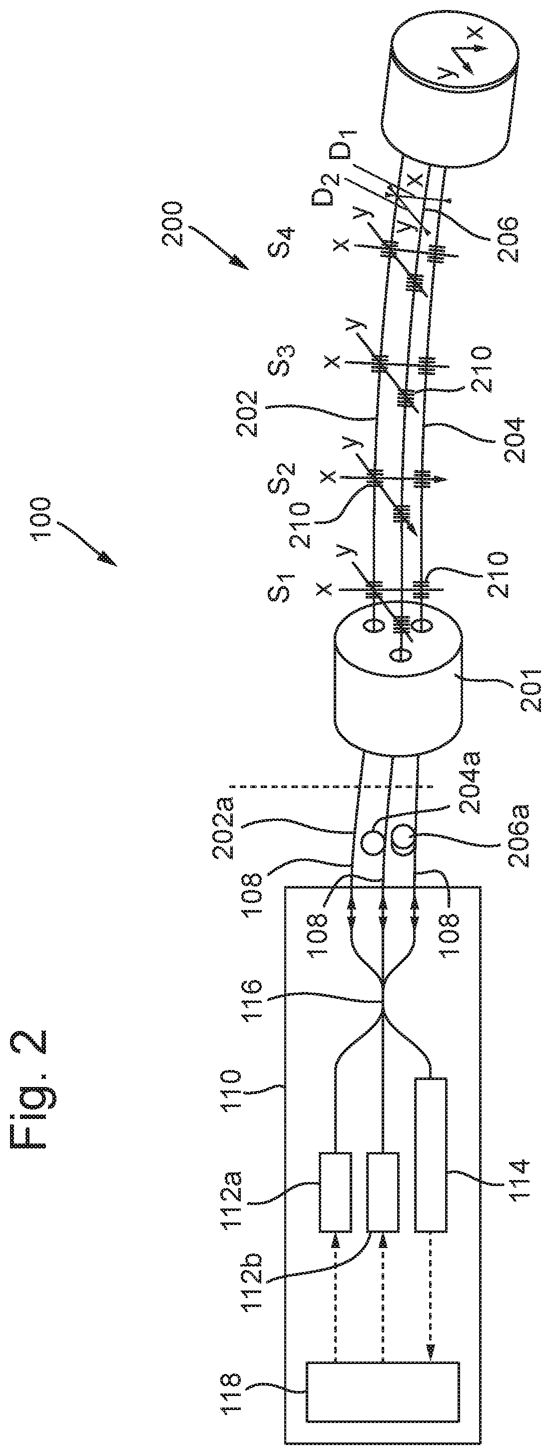
[0050]With reference to FIG. 2, an optical shape sensing system 100 according to arrangements of the present disclosure comprises an interrogation unit 110, and a fibre optic curvature sensor 200.
[0051]The interrogation unit 110 comprises first and second lasers 112a, 112b arranged to provide laser light to the fibre optic curvature sensor 200. The curvature sensor 200 is an interferometric sensing device configured to cause reflections of light from the laser to interfere with one another to produce an interferometric signal.
[0052]Optical fibres 108 extend between the interrogation unit 110 and the fibre optic curvature sensor 200 to carry light from the lasers 112a, 112b to the curvature sensor 200. The optical fibres 108 are also configured to carry the interferometric signal from the fibre optic curvature sensor 200 back to the interrogation unit 110.
[0053]The interrogation unit 110 further comprises a detector 114 arranged to receive the interferometric signal from the fibre optic curvature sensor 200. The detector 114 may comprises a photo detector, or any other sensor capable of detecting the interferometric signal.
[0054]The interrogation unit 110 further comprises a controller 118 configured to process the interferometric signal received by the detector 114 to determine the curvature being sensed by the fibre optic curvature sensor 200. In the arrangement depicted in FIG. 2, the controller 118, e.g. a further module of the controller 118, is configured to control the operation of the lasers 112a, 112b. For example, the controller 118 may be configured to modulate the frequency of light provided by the lasers 112a, 112b and apply a signal multiplexing technique to the laser light, as described below. Alternatively, the interrogation unit 110 may comprise a further controller (not shown) configured to control the operation of the lasers 112a, 112b.
[0055]In the arrangement shown, the curvature sensor 200 comprises first, second and third optical fibre portions 202, 204, 206. The optical fibre portions 202, 204, 206 are cores provided within a multi-core fibre optic cable 201. However, in other arrangements, the first, second and third optical fibre portions 202, 204, 206 may be provided as separate optical fibres.
[0056]As depicted, the interrogation unit 110 comprises a 3×3 optical coupler 116 configured to optically couple the first and second lasers 112a, 122b and the detector 114 to the optical fibres 108. However, other arrangements of optical couplers are also envisaged. For example, the interrogation unit 110 may comprise a 3×1 optical coupler configured to optically couple the first and second lasers and the detector to an optical fibre extending between the interrogation unit and the curvature sensor 200, and a 1×3 optical coupler may be provided, e.g. as part of the curvature sensor 200, to optically couple the optical fibre to the first, second and third optical fibre portions 202, 204, 206.
[0057]In further alternative arrangements, the optical shape sensing system 100 may comprise any other arrangement for optically coupling the laser 112a, 112b and the detector 114 to the fibre optic curvature sensor 200 such that laser light can be sent to the fibre optic curvature sensor 200 by the lasers 112a, 112b and received from the fibre optic curvature sensor 200 by the detector 114. For example, the interrogation unit 110 may comprise an optical circulator configured to direct the interferometric signal received from the fibre optic curvature sensor 200 to the detector 114.
[0058]The second optical fibre portion 204, is spaced apart from the first optical fibre portion 202 in a first direction X by a first predetermined distance D1. The optical fibre portions, e.g. main longitudinal axes of the optical fibre portions, extend in a second direction Z. The first direction X is substantially perpendicular to the second direction Z. In other words, the first direction X is a lateral direction of the optical fibre portions 202, 204, 206.
[0059]The third optical fibre portion 206, is spaced apart from the first optical fibre portion 202 in a third direction Y by a second predetermined distance D2. The second predetermined distance D2 may be the same as the first predetermined distance D1.
[0060]Alternatively, the first and second predetermined distances D1, D2 may differ. As depicted, the third direction Y is a lateral direction of the optical fibre portions, e.g. substantially perpendicular to the second direction Z, and is substantially perpendicular to the first direction X. In other arrangements, the third direction Y may be parallel with the first direction X or comprise components parallel and perpendicular to the first direction X.
[0061]In use of the fibre optic curvature sensor 200, the first, second and third optical fibre portions 202, 204, 206 are supported, e.g. relative to one another, such that the separations between the first and second and first and third optical fibre portions are maintained as the curvature of the sensor 200 changes.
[0062]The first, second and third optical fibre portions 202, 204, 206 each comprise a plurality of reflectors 210 spaced along the lengths of the optical fibre portions. The reflectors may be spaced apart by a spacing distance. The reflectors 210 are configured to reflect a portion of the laser light travelling along the optical fibre portion. The reflectors 210 may comprise Bragg gratings, fibre voids, elements of reflective material embedded in the optical fibre portions or any other suitable form of reflector.
[0063]The reflectors 210 are arranged into sets of reflectors S1, S2, S3, S4, each set of reflectors including a reflector 210 in each of the optical fibre portions 202, 204, 206. The reflectors 210 are spaced along the respective optical fibre portions such that, when the optical fibre portions are in neutral, e.g. uncurved, positions, the reflectors 210 in each of the sets of reflectors S1, S2, S3, S4 are aligned with one another in the second direction Z, e.g. along the axis of the optical fibre portions 202, 204, 206.
[0064]The first, second and third optical fibre portions 202, 204, 206 each comprise respective optical fibre portion delay lengths 202a, 204a, 206a, which comprise lengths of optical fibre that act as delays to the transmission of optical signals along the optical fibre portions 202, 204, 206. The optical fibre portion delay lengths are provided between the interrogation unit 110, e.g. the optical coupler 116, and the reflectors 210.
[0065]Each of the optical fibre portion delay lengths may be unique. The delay length of each of the optical fibre portions may be a multiple of a delay length portion. For example, the first optical fibre portion 202 may have a delay length equal to the delay length portion, the second optical fibre portion 204 may have a delay length of twice the delay length portion and the third optical fibre portion 206 may have a delay length of three times the delay length portion. Alternatively, as depicted in FIG. 2, the first optical fibre portion 202 may have a delay length of 0 (zero), the second optical fibre portion 204 may have a delay length equal to a delay length portion and the third optical fibre portion 206 may have a delay length of twice the delay length portion. Alternatively again, the delay lengths may differ by different amounts between the optical fibre portions.
[0066]The greatest difference in the delay lengths between any pair of the optical fibre portions 202, 204, 206 may be less than the spacing distance between the reflectors along the first, second and third optical fibre portions. This allows the interferences corresponding to reflections of laser light from each of the sets of reflectors S1, S2, S3, S4 to be distinguished from one another when operating the curvature sensor, as described below.
[0067]The fibre optic curvature sensor 200 forms a plurality of interferometers, each comprising a pair of arms. In particular, arms of the interferometers may be defined between the coupling 116 provided within the interrogation unit 110 and each of the reflectors 210 provided in each of the optical fibre portions 202, 204, 206. A portion of the light from the laser travels along each arm of the interferometers and interferes with the portions of the laser light travelling along each of the other arms to produce an interferometric signal comprising light from all of the interferometers. The interferometric signal is detected by the detector 114.
[0068]Due to the delay lengths being provided for each optical fibre portion, when the fibre optic curvature sensor is in a neutral, uncurved position, Optical Path length Differences (OPDs) between the reflectors 210 in each set of reflectors S1, S2, S3, S4 will be equal to the differences in the delay lengths between the corresponding optical fibre portions.
[0069]For example, considering the first set of reflectors S1 depicted in FIG. 2, the OPD of the interference between light reflecting from the reflector in the first optical fibre portion 202 and light reflecting from the reflector in the second optical fibre portion 204 will be equal to the delay length portion and the OPD of the interference between light reflecting from the reflector in the first optical fibre portion 202 and light reflecting from the reflector in the third optical fibre portion 208 will be equal to twice the delay length portion. If the fibre optic curvature sensor 200 remains uncurved along its length, the OPDs of interferences corresponding to reflectors in each of the other sets of reflectors will be the same as the first set S1.
[0070]When the curvature of the fibre optic curvature sensor 200 is changed, the optical fibre portions, e.g. of the first, second and third optical fibre portions 202, 204, 206, which are located closer to an outside of the curve than others of the optical fibre portions, will experience a greater positive strain, e.g. increase in length, than the other optical fibre portions. Similarly, the optical fibre portions, which are located closer to an inside of the curve than others of the optical fibre portions, will experience a greater negative strain, e.g. reduction in length, than the other optical fibre portions.
[0071]For example, if a portion of the curvature sensor is curved in the first direction such that the first optical fibre portion 202 is on the outside of the curve, the first optical fibre portion may experience a positive strain in the area of the curve and the second optical fibre portion may experience a negative strain. The distances between the coupler 116 and the reflectors 210 within the first optical fibre portion at, and further along the optical fibre portion than, the area of the curve are therefore increased compared to the distances between the coupler and the reflectors in corresponding sets of reflectors within the second optical fibre portion. The OPD of the interference between light reflecting from the reflectors in the first and second optical fibre portions, within each set of reflectors in and beyond the area of the curve, therefore varies, e.g. reduces, according to the magnitude of the curvature in the first direction X.
[0072]Since, in the arrangement depicted in FIG. 2, the third optical fibre portion 206 is aligned with the first optical fibre portion 202 in the first direction X, the OPD of interferences between the reflectors in the first and third optical fibre portions may be unchanged when the curvature sensor is curved in the first direction X, e.g. about an axis in the third direction Y. However, if the curvature sensor is curved in the third direction Y, the OPD of interferences between reflectors in the first and third optical fibre portions, within each set of reflectors in and beyond the area of the curve, will change according to the magnitude of the curvature in the third direction Y.
[0073]Hence, by determining the OPDs of interferences corresponding to reflectors in each set of reflectors individually, the magnitude, position and direction of curvature experienced by the fibre optic curvature sensor 200 can be determined.
[0074]With reference to FIG. 3, in order to determine the curvature of the fibre optic curvature sensor 200 based on the interferometric signal received at the detector 114, the controller 118, or another controller, may perform an optical shape sensing method 300 according to arrangements of the present disclosure.
[0075]The method 300 comprises a first step 302, in which the fibre optic curvature sensor 200 is provided. As described above, the first, second and third optical fibre portions 202, 204, 206 of the curvature sensor may be arranged such that the optical fibre portions are spaced apart from one another in the first and third directions X, Y by the first and second predetermined distances D1, D2 respectively.
[0076]The method 300 further comprises a second step 304 in which OPDs between the reflectors in each set of reflectors S1, S2, S3, S4 are determined based on the detected interferometric signal.
[0077]In order to determine the OPDs, e.g. in the second step 304, the method 300 may comprise applying a Range-Resolved Interferometry (RRI) technique. RRI allows the different interferences of light within an interferometric signal to be distinguished from one another based on their OPD. RRI also allows the different OPDs of the interferences within an interferometric signal to be determined.
[0078]The RRI technique is performed by modulating the frequency of laser light produced by the lasers 112a, 112b. The frequency of the laser light may be modulated using a linear modulation function, such as a triangular or saw tooth modulation function. Alternatively, as depicted in the top frame of FIG. 4a, the frequency of the laser light may be modulated using a sinusoidal modulation function F1. Using a sinusoidal modulation function may reduce the complexity of the system due to a reduced number of frequency components within the modulation function.
[0079]The middle frame of FIG. 4a depicts an example of an interferometric signal SIG received at a common detector from two interferometers that have been provided with laser light modulated using the modulation function F1. Each of the interferometers is configured to cause interference of the laser light over a different OPD.
[0080]The detected interferometric signal SIG may be multiplied by a window function. Two examples of windows functions W1 and W2 are shown in the bottom frame of FIG. 3a. The first window function W1 is a square function and the second window function W2 is a smooth window function, such as a Gaussian window function. It is also envisaged that other window functions may be used as desirable.
[0081]With reference to FIG. 4b, in order to determine the relative OPDs of the two interferometers, the detected interferometric signal is transformed into the frequency domain, e.g. by performing a Fourier transform (ƒ) of the interferometric signal. Due to the modulation of the laser light sent to the interferometers, the positions of peaks in the frequency spectrum of the interferometric signal correspond to the OPDs of the interferometers.
[0082]The top frame of FIG. 4b shows a frequency spectrum ƒ(SIG) of the interferometric signal and the bottom frame shows the Frequency spectrums ƒ(SIG·W1) and ƒ(SIG·W2) of the interferometric signals multiplied by the window functions W1 and W2 respectively. As shown, when the smooth window function W2 is applied to the interferometric signal, the peaks in corresponding Frequency spectrum may be more distinct from one another with less interference from side lobes. In the frequency spectrum ƒ(SIG·W2), two peaks are present, the frequencies of the peaks corresponding to the OPDs of the two interferometers.
[0083]As described above, when the curvature sensor is in the neutral, uncurved position, the OPDs of interferences between light reflecting from the reflectors within each particular set of reflectors will be equal to the differences in the delay lengths of the optical fibre portions. The peaks within a frequency spectrum of the interferometric signal are therefore at the same frequencies and it may not be possible to distinguish between the sets of reflectors based on their OPDs.
[0084]Furthermore, if the curvature sensor is curved at an unknown position along the length of the optical fibre portions, such that OPDs of interferences corresponding to one or more of the sets of reflectors change, it may not be possible to determine which of the sets of reflectors is producing the interferences with different OPDs, and hence, it may not be possible to determine where, e.g. along its length, the curvature sensor 200 is experiencing a curvature.
[0085]As described above, the separation distance between the reflectors 210 along each of the optical fibre portions 202, 204, 206 may be greater than the largest delay length.
[0086]Hence, the interferences of reflections from two reflectors that are in different sets of reflectors may have a greater OPD than interferences corresponding to a particular set of reflectors. Interferences caused by reflectors in difference sets of reflectors can therefore be distinguished within the interferometric signal.
[0087]In order to distinguish between the portions of the interferometric signal relating to each set of reflectors, and thereby determine a curvature of the curvature sensor at a particular position along its length, a signal multiplexing technique may be used. The controller 118 or a further controller may be configured to apply the signal multiplexing technique to the light being provided by the lasers 112a, 112b. The signal multiplexing technique may be applied such that portions of the interferometric signal can be distinguished from one another based on a propagation time of the light within the signal.
[0088]In one arrangement, the controller 118 is configured to apply a time division multiplexing technique, in which the lasers 112a, 112b are configured to provide laser light in pulses of a predetermined time period. The frequency of light provided during the pulses is modulated, e.g. using frequency modulation, as described above, such that RRI techniques can be applied to the interferometric signal produced by interferences between reflections of the light pulse.
[0089]The predetermined time period may be selected to be sufficiently long that reflections, of laser light sent within a single pulse, from each of the reflectors within a set of reflectors are received by the detector 114 at substantially the same time, such that interferences between the reflections from each of the reflectors within the set of reflectors can be detected. Additionally, the predetermined time period may be selected to be sufficiently short that interferences between reflections, of the light sent within a particular pulse, from the reflectors within two or more sets of reflectors, do not occur at the same time. When time division multiplexing is used, the gap between pulses may be sufficient to allow the light to be reflected from each of the reflectors 210 along the optical fibre portions 202, 204, 205 and return to the detector 114 before the next pulse is generated. In this way, portions of the interferometric signal, received at the detector 114 that correspond to different sets of reflectors can be distinguished from one another based on the time at which they are received by the detector 114.
[0090]For example, FIGS. 5a, 5b, 5c and 5d depict simplified frequency spectrums of the interferometric signal being received from the optical curvature sensor 200 at times T1, T2, T3 and T4 respectively, with frequency increasing along the horizontal axis. At time T1, the detector is receiving reflections from the reflectors in set S1; at time T2, the detector is receiving reflections from the reflectors in set S2; at time T3, the detector is receiving reflections from the reflectors in set S3 and at time T4, the detector is receiving reflections from the reflectors in set S4.
[0091]As depicted in FIGS. 5a and 5b, the positions of peaks within the frequency spectrums at times T1 and T2 are the same, indicating that there is no net curvature of the curvature sensor 200 between the reflectors in set S1 and set S2 along the optical fibre portions 202, 204, 206. The position of the lower frequency peak P1 corresponds to the difference in the delay lengths between the first and second optical fibre portions and the position of the higher frequency peak P2 corresponds to the difference in the delay lengths between the first and third optical fibre portions 202, 206.
[0092]With reference to FIG. 5c, the positions of the peaks within the frequency spectrum at time T3 are however different, indicating that the curvature sensor 200 is measuring a curvature along the optical fibre portions 202, 204, 206 between the reflectors in sets S2 and S3. More particularly, the lower frequency peak P1 is at a reduced frequency (compared to at T1 and T2), indicating a reduction in the OPD between reflectors in the first and second optical fibre portions 202, 204 and therefore a curvature of the sensor 200 in the first direction X with the first optical fibre portion 202 being on the outside of the curve. The higher frequency peak is at an increased frequency, indicating an increase in the OPD between the first and third optical fibre portion and therefore a curvature of the sensor 200 in the third direction Y with the first optical fibre 202 portion being on the inside of the curve.
[0093]As shown in FIG. 5d, the positions of the peaks within the frequency spectrum at time T4 are the same as at time T3, indicating that there is no net curvature of the curvature sensor 200 between the reflectors in set S3 and set S4.
[0094]Returning to FIG. 3, the method 300 further comprises a third step 306, in which a curvature of the curvature sensor, e.g. the optical fibre portions provided within the curvature sensor, is determined based on the optical path length differences, between the reflectors.
[0095]The curvature of the curvature sensor 200 is determined in the third step 306 by considering the differences in the OPDs corresponding to each set of reflectors, e.g. by comparing the positions of peaks within frequency spectrums of the interferometric signals received at successive points in time.
[0096]The controller 118 is thereby able to determine a shape of the curvature sensor 200 from the magnitude and direction of curvature between each set of reflectors along the fibre optic curvature sensor 200. If the curvature sensor 200 is attached to an object, the curvature sensor 200 can therefore be used to determine a shape or change in shape of the object.
[0097]In the method 300 described above, time division multiplexing is used to enable the portions of the received interferometric signal corresponding to each of the sets of reflectors to be distinguished from one another based on a time at which the portion of the signal is received. However, in other arrangements alternative multiplexing techniques may be used. For example, a code-division multiplexing technique may be used. The code-division multiplexing technique may be applied using a repeating code the length of which corresponds to the predetermined time period. In this way, portions of the interferometric signal corresponding to each of the set of reflectors can be distinguished within the interferometric signal by demultiplexing the signal using an appropriate delay, e.g. corresponding to times T1, T2, T3 and T4.
[0098]Using a code division multiplexing technique allows light to be supplied constantly, without gaps between the time periods.
[0099]Alternatively again, any other signal multiplexing or signal processing technique may be used that enables portions of a received signal to be distinguished based on the propagation time of the signal portions.
[0100]In the arrangement depicted, the fibre optic curvature sensor 200 comprises three optical fibre portions 202, 204, 206. As described above, the second optical fibre portion 204 is spaced apart from the first optical fibre portion 202 in the first direction X and the third optical fibre portion 206 is spaced apart from the first optical fibre portion 202 in the third direction Y, which is perpendicular to the first direction X. Hence, the fibre optical curvature sensor 200 is capable of determining curvature in two perpendicular directions.
[0101]In other arrangements, the fibre optic curvature sensor 200 may comprise a fourth optical fibre portion configured similarly to the first, second and third optical fibre portions 202, 204, 206 and spaced apart from the first optical fibre portion 202 in a direction having components in the first and third directions X, Y. The fourth optical fibre portion may have a delay length that is different to the first, second and third optical fibre portions 202, 204, 206. The OPDs of interferences between light reflecting from reflectors in the first and fourth optical fibre portions may be used when determining curvatures in the first and/or third directions.
[0102]Alternatively, in other arrangements, the fibre optic curvature sensor 200 may not comprise the third optical fibre portion 206 and may be configured to measure curvatures only in the first direction X.
[0103]Furthermore, although in the arrangement depicted, four sets of the reflectors are provided, it will be appreciated that the fibre optic curvature sensor 200 may be extended to include any desirable number of sets of reflectors.
[0104]Measurements made using interferometric systems may have a limited unambiguous measurement range corresponding to the range over which the difference in phase between the interfering light varies by 2π radians. If a measurement being made is known to exceed the unambiguous range of the interferometric measurement device, it may not be possible to rely exclusively on the result of the interferometric measurement, as is not possible to determine a total difference in phase between the interfering light.
[0105]In the case of the optical shape sensing system 100, the unambiguous range may correspond to a change in curvature of the curvature sensor 200, e.g. from a neutral, uncurved position of the curvature sensor, that is less than a maximum curvature that it is desirable to measure using the sensor.
[0106]During continuous periods of use of the curvature sensor 200, changes in curvature between measurement points, may be within the unambiguous range of the system 100, so that changes in curvature can be accurately determined. However, when the system is initially started, if the curvature of the curvature sensor 200 could be greater than the unambiguous range of the system 100, the initial curvature of the curvature sensor 200 cannot be reliably determined.
[0107]In the arrangement depicted in FIG. 2, first and second lasers 112a, 112b are provided. The first and second lasers 112a, 112b may be configured to provide light of different wavelengths. Additionally, the first and second lasers 112a, 112b may be operated, e.g. by the controller 118, such that light from each of the lasers can be distinguished from one another within the interferometric signal received by the detector 114. For example, the light from the lasers may be multiplexed using the signal multiplexing technique or another signal multiplexing technique.
[0108]The lasers 112a, 112b may be operated to enable the system 100 to use a two-wavelength interferometry technique. Two-wavelength interferometry techniques can be used to increase the unambiguous range of the interferometry system by combining interferometric signals at different wavelengths. In particular, the unambiguous range may be increased such that the unambiguous range is equal to or greater than the desired operating range of the system 100, e.g. a maximum desirable curvature to be measured using the curvature sensor 200. Hence, using the two lasers enables the initial curvature of the curvature sensor to be determined reliably when the system 100 is initially started.
[0109]In other arrangements, the system 100 may comprises three or more lasers and the system may be configured to use a multi-wavelength interferometry technique in a similar way to the two-wavelength interferometry technique. Alternatively, in some arrangements, e.g. if it is only desirable to determine changes in curvature, the second laser 112b may be omitted.
[0110]In one application of the optical shape sensing system 100, the fibre optical curvature sensor 200 may be coupled to a surface of or provided within an aerofoil, such as a wing or a propeller or rotor blade for an aircraft. The optical shape sensing system 100 may be used to measure the shape and changes in shape of the aerofoil during testing of the aerofoil and/or operation of the aircraft.
[0111]It will be appreciated by those skilled in the art that although the invention has been described by way of example, with reference to one or more exemplary examples, it is not limited to the disclosed examples and that alternative examples could be constructed without departing from the scope of the invention as defined by the appended claims.
PUM


Description & Claims & Application Information
We can also present the details of the Description, Claims and Application information to help users get a comprehensive understanding of the technical details of the patent, such as background art, summary of invention, brief description of drawings, description of embodiments, and other original content. On the other hand, users can also determine the specific scope of protection of the technology through the list of claims; as well as understand the changes in the life cycle of the technology with the presentation of the patent timeline. Login to view more.