Eureka AIR delivers breakthrough ideas for toughest innovation challenges, trusted by R&D personnel around the world.

Augment And Means For Connecting the Same To A Joint Prosthesis

Active Publication Date: 2021-01-14
HOWMEDICA OSTEONICS CORP
View PDF6 Cites 0 Cited by
  • Summary
  • Abstract
  • Description
  • Claims
  • Application Information

AI Technical Summary

Benefits of technology

The patent describes an orthopedic system with an augment and a femoral prosthesis that can be connected together using a fastener. The augment has a through-bore and a recessed slot for connection, and the femoral prosthesis has a condylar portion and a bone-facing side with a bore for receiving the fastener. The through-bore and recessed slot align to create a secure connection between the augment and femoral prosthesis, and the bone-facing side of the femoral prosthesis contacts the augment when connected. This system allows for precise positioning and stable connection between the augment and femoral prosthesis during surgery.

Problems solved by technology

Any one of these compartments or combination of compartments can become damaged or diseased.
For example, osteoarthritis can destroy articular cartilage within the tibiofemoral and / or patellofemoral joints producing painful bone-on-bone articulation and malalignment of the knee.
Continued arthritic changes of the joint over time often results in changes to the quality of the bone as well as deterioration of the strength and efficacy of the ligamentous structures.
Amongst the many drawbacks associated with revision knee surgery is the loss of bone associated with the explantation of the prior components which may be compounded by underlying disease.
Thus, significant condylar defects oftentimes present themselves upon explantation.
However, such means currently available may be limited by the geometry of the augment and / or the associated joint prosthesis.
Accordingly, such means may be either too time consuming to manipulate resulting in extended procedure times or do not sufficiently connect to the joint prosthesis.

Method used


Image

  • Augment And Means For Connecting the Same To A Joint Prosthesis
  • Augment And Means For Connecting the Same To A Joint Prosthesis
  • Augment And Means For Connecting the Same To A Joint Prosthesis

Examples


Embodiment Construction

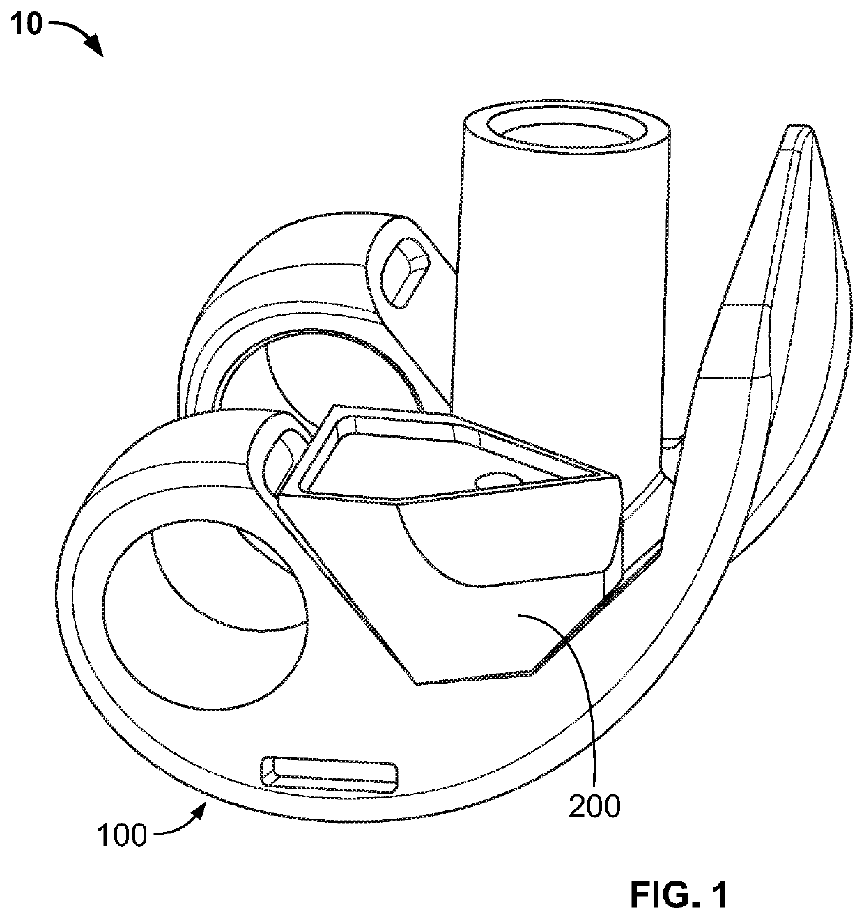
[0021]When referring to specific directions in the following discussion of certain implantable joint replacement devices, it should be understood that such directions are described with regard to the orientation and position of the implantable joint replacement devices during exemplary application to the human body. Thus, as used herein, the term “proximal” means closer to the heart and the term “distal” means further from the heart. The term “anterior” means toward the front part of the body or the face, and the term “posterior” means toward the back of the body. The term “medial” means toward the midline of the body, and the term “lateral” means away from the midline of the body. The term “inferior” means toward the feet of the body, and the term “superior” means toward the head of the body. Further, as used herein, the terms “about,”“generally,” and “substantially” are intended to mean deviations from absolute are included within the scope of the term so modified.

[0022]Referring ...


PUM


Abstract

An orthopedic system includes an augment that includes a proximal surface and a distal surface, a recessed slot extending along the distal surface, and a through-bore extending between the proximal and distal surfaces and intersecting the slot. The system also includes a coupling component that includes a head and a body. The head has an aperture and is configured to be slidingly received by the recessed slot wherein, when the head is received within the recessed slot, the aperture aligns with the through-bore. The system further includes a femoral prosthesis that has an articular side that defines condylar portions and a bone facing side opposite the articular side. The bone facing side defines a coupling bore. The coupling bore is configured to receive the body of the coupling component for connection thereto.

Description

CROSS-REFERENCE TO RELATED APPLICATIONS[0001]This application claims the benefit of the filing date of U.S. Provisional Patent Application No. 62 / 872,843, filed Jul. 11, 2019, the disclosure of which is hereby incorporated herein by reference.BACKGROUND OF THE INVENTION[0002]The knee joint consists generally of three distinct regions, the medial tibiofemoral compartment, the lateral tibiofemoral compartment and the patellofemoral compartment. Any one of these compartments or combination of compartments can become damaged or diseased. For example, osteoarthritis can destroy articular cartilage within the tibiofemoral and / or patellofemoral joints producing painful bone-on-bone articulation and malalignment of the knee.[0003]Knee replacement surgery can be tailored to treat the specific condition diagnosed. For example, for patients with isolated compartmental disease, a partial knee replacement or partial knee arthroplasty (“PKA”) procedure may be performed, such as unicompartmental k...

Claims


Application Information

Patent Timeline
IPC IPC(8): A61F2/30A61F2/38
CPCA61F2/30734A61F2002/30433A61F2002/30736A61F2/3859A61F2/385
Inventor SERVIDIO, DAMON J.
Owner HOWMEDICA OSTEONICS CORP
Why Eureka
Eureka Blog
Learn More