Vehicle-based charging system for electric vehicles

a charging system and electric vehicle technology, applied in the direction of electric propulsion mounting, battery/fuel cell control arrangement, transportation and packaging, etc., can solve the problems of electric vehicle charging infrastructure, electric vehicle charging difficulty, and high voltage dc charging stations, which can be difficult to charge electric vehicles, and require significant grid upgrades and trenching

Active Publication Date: 2021-01-14
MERCEDES-BENZ RES & DEV NORTH AMERICA +1
View PDF0 Cites 6 Cited by
  • Summary
  • Abstract
  • Description
  • Claims
  • Application Information

AI Technical Summary

Benefits of technology

[0004]According to an embodiment, there is a vehicle configured to charge other electric vehicles. The vehicle includes a battery with a number of battery cells, the battery being configured to output direct current at a first voltage. The vehicle also includes a direct current voltage converter configured to convert direct current received from the battery to a second voltage and an electrical connector in electrical communication with the direct current voltage converter, the electrical connector being configured to supply direct current at the second voltage from the direct current voltage converter to an electric vehicle. The vehicle further includes a control system configured to determine a charging voltage of an electric vehicle, and operate the direct current voltage converter to output direct current at a second voltage corresponding to the charging voltage of the electric vehicle, and a thermal management system configured to maintain the battery within a selected temperature range.

Problems solved by technology

Many areas do not have electric vehicle charging infrastructure, making it difficult to charge electric vehicles.
Electric vehicle charging infrastructure, and particularly high voltage DC charging stations, can also be expensive to install, and can require significant grid upgrades and trenching.
Such systems provide low energy transfer rates, which increases the time required to charge the electric vehicle, and waste a significant amount of power converting between direct current and alternating current multiple times. Accordingly, there exists a need for improved mobile systems for charging electric vehicles.

Method used


Image

  • Vehicle-based charging system for electric vehicles
  • Vehicle-based charging system for electric vehicles
  • Vehicle-based charging system for electric vehicles

Examples


example 1

age DC-DC Charging System

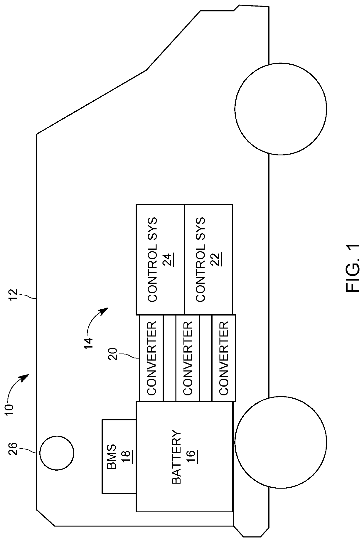
[0036]The following example describes an exemplary embodiment of a DC-DC charging system capable of accepting 65 KW DC charge and discharging (off-charging) into an electric vehicle (EV) at 50 KW DC rate. Operating conditions may include a temperature range of 0 to 40 Celsius. The system can be mounted inside a van, but may be implemented in any setting mobile or stationary. The system can charge EVs with a voltage range of 200V to 600V, such as 260V to 410V, depending on the battery configuration. Off-charging can be compatible for EVs with J1772 CCS type 1 DC fast charge ports, or other charging ports.

[0037]In certain embodiments the system charging voltage can be 600V. The system off-charging voltage (e.g., when charging an electric vehicle) can be 260V-410V, depending on the particular vehicle.

[0038]The charging functionality of the system in the van can work with the following specifications. The system can be equipped with a J1772 CCS type 1 port, whic...

example 2

omputing Environment

[0049]FIG. 9 and the following discussion are intended to provide a brief, general description of an exemplary computing environment in which the disclosed control system technology may be implemented. For example, the methods and processes described herein can be carried out by a controller or processor configured similarly to the computing environment described below. Moreover, the disclosed technology may be implemented with other computer system configurations, including hand held devices, digital signal processors (DSPs), multiprocessor systems, microprocessor-based or programmable consumer electronics, network PCs, minicomputers, mainframe computers, and the like. The disclosed technology may also be practiced in distributed computing environments where tasks are performed by remote processing devices that are linked through a communications network.

[0050]With reference to FIG. 9, an exemplary system for implementing the disclosed technology includes a gene...


PUM


Abstract

A vehicle is configured to charge other electric vehicles. The vehicle includes a battery with a number of battery cells, the battery being configured to output direct current at a first voltage. The vehicle also includes a direct current voltage converter configured to convert direct current received from the battery to a second voltage and an electrical connector in electrical communication with the direct current voltage converter, the electrical connector being configured to supply direct current at the second voltage from the direct current voltage converter to an electric vehicle. The vehicle further includes a control system configured to determine a charging voltage of an electric vehicle, and operate the direct current voltage converter to output direct current at a second voltage corresponding to the charging voltage of the electric vehicle, and a thermal management system configured to maintain the battery within a selected temperature range.

Description

CROSS-REFERENCE TO RELATED APPLICATIONS[0001]This application claims priority under 35 U.S.C. § 119 to U.S. Provisional Application No. 62 / 872,166, filed on Jul. 9, 2019, the entire disclosure of which is herein expressly incorporated by reference.FIELD[0002]The present disclosure pertains to mobile, vehicle-based charging systems for electric vehicles.BACKGROUND[0003]Many areas do not have electric vehicle charging infrastructure, making it difficult to charge electric vehicles. Electric vehicle charging infrastructure, and particularly high voltage DC charging stations, can also be expensive to install, and can require significant grid upgrades and trenching. Mobile electric vehicle charging systems allow the charging equipment to be brought to the location of the electric vehicle on demand. However, existing mobile electric vehicle charging systems convert direct current supplied by a battery to alternating current which is supplied to the electric vehicle. The system on the elec...

Claims


Application Information

Patent Timeline
Patent Type & Authority Applications(United States)
IPC IPC(8): B60L58/24H02J7/00H02J7/34B60L53/62B60K1/04
CPCB60L58/24H02J7/007H02J7/342B60K2001/005B60L53/62B60K1/04H02J2207/20H02J7/0045Y02T10/70Y02T10/7072Y02T90/12Y02T90/16H02J2310/48H02J7/0048
Inventor GAZE, JENNIFERPERSIN, JASONAHMAD, ARFAN
Owner MERCEDES-BENZ RES & DEV NORTH AMERICA
Why Eureka
Try Eureka