Programmable power amplifier

a power amplifier and programmable technology, applied in power amplifiers, amplifiers, gain control, etc., can solve the problems of difficult linear power control of output power, manufacturing process tolerances and power supply voltage variations, and existing power amplifier control techniques are sensitive to temperature, so as to maintain the power level across the operational temperature range. high precision

Active Publication Date: 2020-04-02
EM MICROELECTRONIC-MARIN
View PDF0 Cites 2 Cited by
  • Summary
  • Abstract
  • Description
  • Claims
  • Application Information

AI Technical Summary

Benefits of technology

[0004]An object of the present invention is to overcome at least some of the above shortcomings of existing power amplifiers. More specifically, the present invention aims to improve upon the ability to set the output power in a power amplifier with high precision and to maintain the power level across the operational temperature range.
[0010]The proposed solution has the advantage that the proposed amplifier operates in a low current and voltage arena. Furthermore, the output power is highly accurate, and the programmable power output step size is less than 0.5 dB. Optionally, programmable waveform shaping may also be included to allow maximum flexibility in meeting governmental bandwidth requirements. Furthermore, by attaching the output of the power amplifier to an inductor that is also connected to a power supply and to an RF matching network, the current output from the amplifier generates a voltage across the inductor and thus RF power. This may be used to allow the power amplifier output power to be independent of power supply (for instance a battery voltage) until the power supply or more specifically the supply voltage falls below a set brown out level. As explained later on, a further advantage is that temperature stability of the amplifier may be tied to bandgap voltage stability.

Problems solved by technology

Nevertheless, existing power amplifier control techniques are sensitive to temperature, manufacturing process tolerances and power supply voltage variations.
Furthermore, it is difficult to have a linear power control of the output power and to achieve output power steps of 0.5 dB or smaller.

Method used


Image

  • Programmable power amplifier
  • Programmable power amplifier

Examples


Embodiment Construction

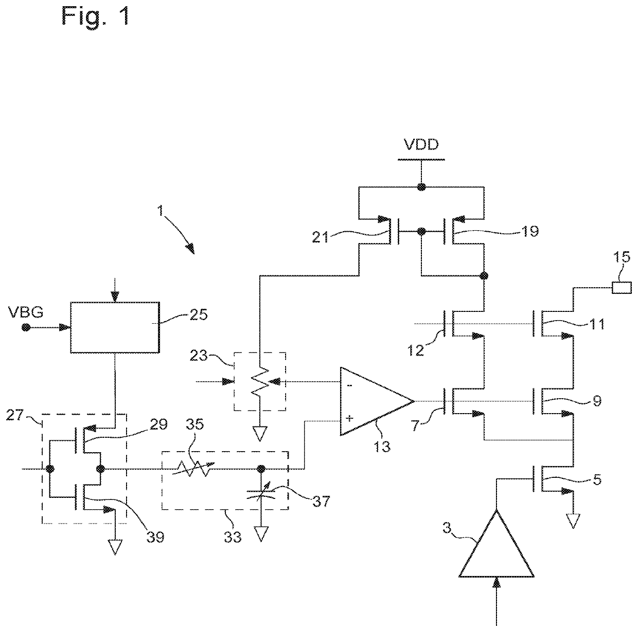
[0022]An embodiment of the present invention will now be described in detail with reference to the attached figures. The invention will be described in the context of a programmable precision power-controlled RF amplifier, also referred to simply as a power amplifier. However, the teachings of the invention are not limited to this environment or application. Identical or corresponding functional and structural elements which appear in different drawings are assigned the same reference numerals. As utilized herein, “and / or” means any one or more of the items in the list joined by “and / or”. As an example, “x and / or y” means any element of the three-element set {(x), (y), (x,y)}. In other words, “x and / or y” means “one or both of x and y.” As another example, “x, y, and / or z” means any element of the seven-element set {(x), (y), (z), (x,y), (x,z), (y,z), (x,y,z)}. In other words, “x, y and / or z” means “one or more of x, y, and z.” Furthermore, the term “comprise” is used herein as an o...


PUM


Abstract

The present invention concerns a programmable power amplifier comprising:an amplifier core transistor circuit connected to an amplifier output node; a switch connected to the amplifier core transistor circuit, the switch being configured to switch on and off the amplifier core transistor circuit; and a feedback circuit of the amplifier core transistor circuit. The feedback circuit comprises a digital-to-analog converter and an operational amplifier having a first input node configured to receive a first reference signal; a second input node connected to the digital-to-analog converter; and an output node for outputting an operational amplifier output signal and connected to the amplifier core transistor circuit for controlling the amount of current flowing in the amplifier core transistor circuit. The digital-to-analog converter has a programmable resistance value for controlling the resistance of the digital-to-analog converter to thereby adjust a digital-to-analog converter output signal fed to the second input node of the operational amplifier for controlling an amplifier output signal at the amplifier output node.

Description

TECHNICAL FIELD[0001]The present invention relates to a programmable power amplifier. More specifically, the invention relates to a programmable precision power-controlled radio frequency (RF) amplifier. The invention also relates to a method of operating the proposed power amplifier.BACKGROUND OF THE INVENTION[0002]An RF power amplifier is a type of electronic amplifier that converts a low-power RF signal into a higher power signal. RF power amplifiers are typically used to drive the antenna of a transmitter. Product manufacturers often have a need to control output power from RF power amplifiers. This allows them to optimize performances such as transmission range and battery life and at the same time not to violate government regulations dealing with power emissions. For that purpose, power amplifiers known in the art are usually based on methods that control gate or base drive, adjust bias current or parallel devices together performing power control.[0003]Nevertheless, existing...

Claims


Application Information

Patent Timeline
Patent Type & Authority Applications(United States)
IPC IPC(8): H03F3/217H03F3/72H03F3/24
CPCH03F2200/451H03F2200/252H03F3/24H03F3/72H03F2203/7221H03F3/2175H03F3/245H03F2200/18H03F2200/165H03F2200/327H03F2200/462H03F2200/75H03G3/3042H03F1/301H03F1/223H03F3/193H03C1/12
Inventor ROTZOLL, ROBERT R.BUESCHER, KEVIN SCOTT
Owner EM MICROELECTRONIC-MARIN
Why Eureka
Try Eureka