Procedure for maneuvering a hybrid aerodyne of vtol or stol

a hybrid aerodyne and aerodyne technology, applied in the direction of vertical landing/take-off aircraft, process and machine control, instruments, etc., can solve the problems of aerodynamic instability, no such system has been genuinely developed and commercialized, and the mechanisms that have been proposed are too complex, etc., to achieve sufficient lift and shorten the rigidity

Active Publication Date: 2021-01-14
INNOSTAR
View PDF0 Cites 2 Cited by
  • Summary
  • Abstract
  • Description
  • Claims
  • Application Information

AI Technical Summary

Benefits of technology

[0004]No such system has been genuinely developed and made commercially available. The reasons that have led to the failure of such systems and that lead to a better understanding of the advantage of the present invention, are believed to be as follows:
[0005]if the rotary wing is to be aerodynamically “hidden” in horizontal flight, the mechanisms that have been proposed are too complex, and that operation includes stages of aerodynamic instability both at the time the wing is being stowed, after takeoff and while transitioning to cruising flight, and also at the time it is being deployed for landing; and
[0006]if the rotor is not hidden in cruising flight and is left free in the air stream (or “relative airflow”), then, in order to have satisfactory takeoff power, one of two things apply:
[0007]either the rotor has a diameter that is large, and consequently has blades of considerable length, which leads to instabilities when stopping and / or restarting rotation of the rotor while the rotor does not have the stabilizing effect of centrifugal force. Specifically, in order to be aerodynamically efficient, the blades of the rotor need to be relatively fine, and thus relatively flexible, and they need to present good aeroelastic performance, like the blades of modern helicopter rotors; or
[0008]else use must be made of blades that are shorter and more rigid, and thus more stable, but then the power needed to provide sufficient lift is very high, which undermines the advantage of the concept.
[0009]The invention relates to an aerodyne having at least two single-blades that are spaced apart longitudinally along the roll axis of the aircraft, e.g. as shown in FIGS. 16a and 16b of Document WO2017 / 021608.

Problems solved by technology

No such system has been genuinely developed and made commercially available.
if the rotary wing is to be aerodynamically “hidden” in horizontal flight, the mechanisms that have been proposed are too complex, and that operation includes stages of aerodynamic instability both at the time the wing is being stowed, after takeoff and while transitioning to cruising flight, and also at the time it is being deployed for landing; and
Specifically, in order to be aerodynamically efficient, the blades of the rotor need to be relatively fine, and thus relatively flexible, and they need to present good aeroelastic performance, like the blades of modern helicopter rotors; orelse use must be made of blades that are shorter and more rigid, and thus more stable, but then the power needed to provide sufficient lift is very high, which undermines the advantage of the concept.

Method used


Image

  • Procedure for maneuvering a hybrid aerodyne of vtol or stol
  • Procedure for maneuvering a hybrid aerodyne of vtol or stol

Examples


Embodiment Construction

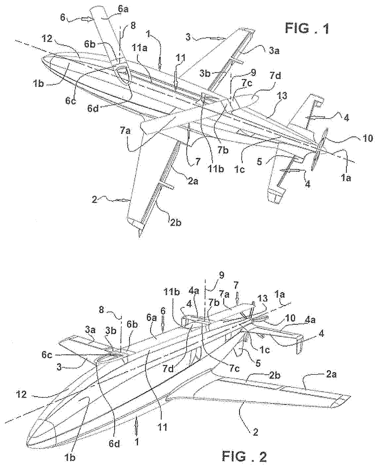
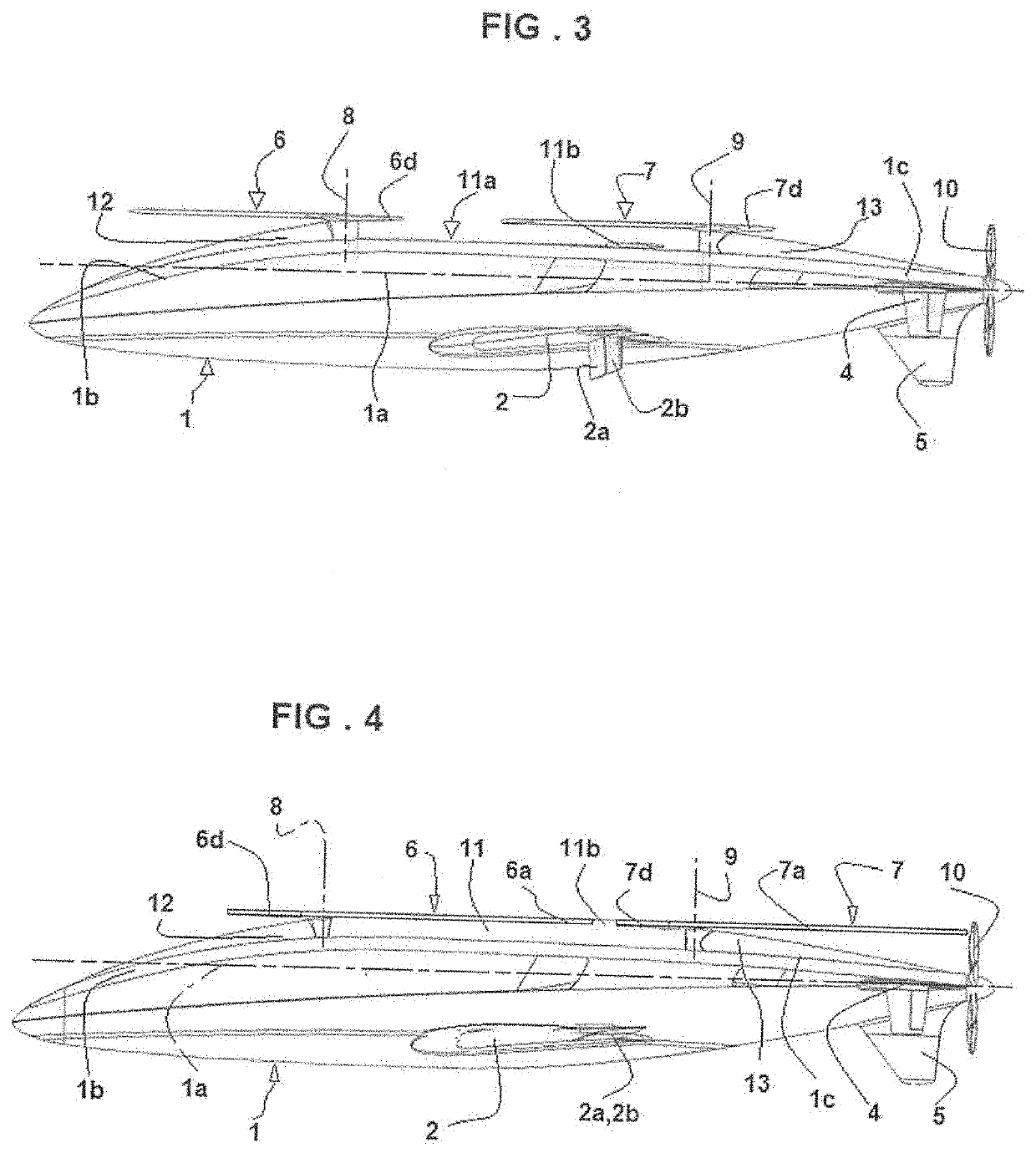
[0042]The aerodyne shown in the figures comprises a fuselage 1 with its roll axis referenced 1a. The fuselage is fitted with a fixed wing comprising main wings 2 and 3, an upside-down U-shaped tail 4, and a tail fin 5, in conventional manner well-known to the person skilled in the art. It should be observed that the wings 2 and 3 possess respective control surfaces 2a, 1b and 3a, 3b shown extending down in FIGS. 1 and 3 and in service in FIGS. 2 and 4. In known manner, the horizontal branches of the tail also include control surfaces 4a. In the embodiment shown in the figures, the aerodyne of the invention has a front single-blade 6 and a rear single-blade 7. The front single-blade 6 has an active blade 6a that generates lift while it is rotating. This single-blade is made up both of a first portion 6b that carries said active blade and that constitutes the connection between the active blade and a rotor mast 8, and also of a second portion 6c that carries the counterweight 6d and t...


PUM


Abstract

An aerodyne comprises a fuselage, a fixed wing , a thruster for cruising flight, and a rotary wing for stages of vertical flight and held stationary during cruising flight. The rotary wing includes at least two contrarotating single-blades disposed at the top of the fuselage and hinged about respective axes perpendicular to the rotor axes of rotation. A maneuvering procedure for maneuvering the aerodyne includes a transition stage between a stage of vertical flight and a stage of cruising flight, wherein in the transition stage, when the speed of each single-blade is less than a threshold speed of rotation, the pitch of each single-blade is such that it no longer provides any lift force and the transverse hinge of the single-blade to its rotor axis is held locked in a position such that the single-blade is perpendicular to the rotor shaft.

Description

[0001]The invention relates to a vertical or short takeoff and / or landing (VTOL or STOL) hybrid aerodyne, of medium-sized drone type capable of high-speed and / or long-range cruising flight. The aerodyne is of the type that is fitted both with a fixed wing associated with a propulsion system for cruising flight and also with a rotary wing for stages of vertical flight and suitable for being kept stationary in cruising flight. The term “medium-sized” is used to designate an aerodyne for which one of the main requirements is long endurance in flight, e.g. for coastal surveillance missions.BACKGROUND OF THE INVENTION[0002]The invention lies within a state of the art that is numerous and varied, e.g. such as that described in Document WO2017 / 021608.[0003]The idea of using one or more single-blade rotors (“single-blades”) in hybrid VTOL “stoprotor” designs is a very old idea. Specifically, a single-blade presents a manifest advantage concerning the drag of the rotary wing while its rotati...

Claims


Application Information

Patent Timeline
Patent Type & Authority Applications(United States)
IPC IPC(8): G05D1/10B64C27/22B64C27/26B64C27/30B64C27/473B64C29/00
CPCG05D1/102B64C27/22B64C29/0025B64C27/30B64C27/473B64C27/26B64C27/08
Inventor SIMON
Owner INNOSTAR
Why Eureka
Try Eureka