Fender arrangement for docking a marine vessel with a boat landing of a marine off-shore structure

a marine vessel and off-shore technology, which is applied in the direction of mooring equipment, hulls, vessel construction, etc., can solve the problems of large amount of fuel used, rapid friction wear of the fender block, and the extra fuel costs involved in the docking procedure. , to achieve the effect of less power, less complex and costly, and minimal maintenance costs

Active Publication Date: 2021-01-21
NORTHERN OFFSHORE SERVICES AB
View PDF0 Cites 0 Cited by
  • Summary
  • Abstract
  • Description
  • Claims
  • Application Information

AI Technical Summary

Benefits of technology

[0006]It is the object of the present invention to alleviate the above mentioned problems by providing a fender arrangement which requires considerably less power in the docking procedure than known “push-to hold” docking solutions and is less complex and costly than fender units with mechanical gripping arms. The invention still offers a mechanically simple and robust fender design that will withstand the harsh operating conditions in an offshore environment with minimal maintenance costs. Hence, the invention provides a fender arrangement for docking a marine vessel with a boat landing of a marine offshore structure such as a wind power plant, including at least one fender unit composed of elastically deformable material and provided with a receiving recess for a docking rail of said boat landing, The fender arrangement is especially characterized in that that the fender unit exhibits an internal deformation control cavity positioned at a distance from the receiving recess within the fender unit and extending at least along the width of said receiving recess, controlling deformation of the fender unit into forming a gripping hold of a docking rail by compression of the internal deformation control cavity when the fender unit is pressed against the docking rail.

Problems solved by technology

The demanding weather conditions also make it a real challenge to service and maintain the structures in a safe and efficient way.
In heavy seas there are substantial forces involved as the service vessel approaches the boat landing and due to sudden heaving motions causing the fenders of the service vessel to slide along the docking rails.
A problem with the traditional fender blocks is that they require the service vessel to constantly press against the wind power plant with considerable power in order to stay docked with the docking rails during the personnel transfer.
This results in large quantities of fuel having to be used just for maintaining the vessel in docking position.
Considering the large amount of individual wind power plants to be serviced in a typical wind power plant site, the extra fuel costs involved for the docking procedures are considerable.
This type of “push-and-hold” docking procedure without any gripping action on the docking rails also results in rapid friction wear of the fender blocks due to vertical sliding movement against the docking rails.
A problem with such a device is the potential vulnerability of the numerous mechanical components in a very harsh work environment.
Complex arrangements like this also tend to be costly.

Method used


Image

  • Fender arrangement for docking a marine vessel with a boat landing of a marine off-shore structure
  • Fender arrangement for docking a marine vessel with a boat landing of a marine off-shore structure
  • Fender arrangement for docking a marine vessel with a boat landing of a marine off-shore structure

Examples


first embodiment

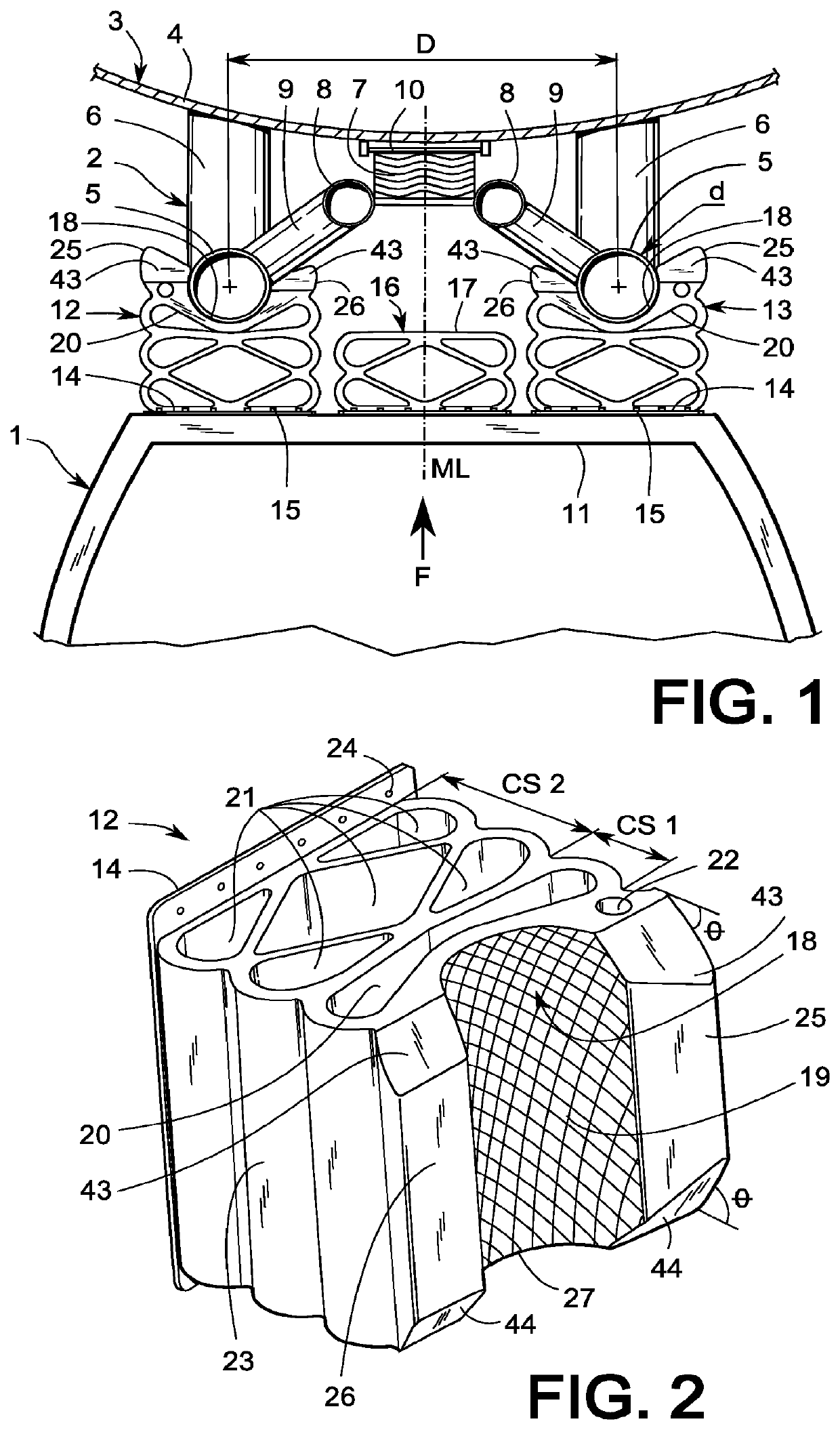
[0048]In order to save even more weight, the fender unit 12 in the shown first embodiment further has a through-going weight-saving cavity 22 which extends in parallel with the internal deformation control cavities 20 and 21. This embodiment also exhibits accordion-shaped or “bellows-shaped” curved sides 23, the purpose of which are to control the compression characteristics of the fender unit 12 together with the correspondingly shaped internal deformation control cavities 20 and 21 inside the fender unit 12. The mounting console 14 is made of metal and is conveniently used as a base surface in the molding process of the remaining fender unit 12. Prior to molding, the mounting console 14 is sand blasted to obtain a rough surface and a coat of primer is applied. Then the polyurethane material is molded directly onto the mounting console 14 and bonds to its surface. The mounting console 14 is also provided with multiple mounting holes 24 for mounting the fender unit 12 to a marine ve...

second embodiment

[0058]FIG. 9 shows a third alternative embodiment having the same outer contour as the This one is also provided with three primary deformation control cavities 20, but has only and four secondary deformation control cavities 21.

fourth embodiment

[0059]FIG. 10 illustrates a fourth alternative embodiment with convex sides 30, giving the fender a rounded, bulging shape. It is provided with four primary deformation control cavities 20, nine secondary deformation control cavities 21 and two weight—saving cavities 22. The primary deformation control cavities 20 and the secondary deformation control cavities 21 both diamond-shaped and triangular. FIG. 11 shows a fifth alternative embodiment having the same outer contour as the This one is provided with three primary deformation control cavities and three secondary deformation control cavities 21. The three secondary deformation control cavities 21 extend from side to side of the fender unit 12. More embodiments of the fender units 12 are feasible within the inventive concept limited only by the accompanying claims, but are not shown per se.

[0060]FIG. 12 shows a sixth alternative embodiment of the invention wherein the receiving recess 18 of the fender unit is provided with multip...


PUM


Abstract

Fender arrangement for docking a marine vessel (1) with a boat landing (2) of a marine offshore structure (3) such as a wind power plant, including at least one fender unit (12, 13) composed of elastically deformable material and provided with a receiving recess (18) for a docking rail (5) of said boat landing (2). The fender arrangement is especially characterized in that fender unit (12, 13) exhibits an internal deformation control cavity (20) positioned at a distance from the receiving recess (18) within the fender unit (12, 13) and extending at least along the width of said receiving recess (18), controlling deformation of the fender unit (12, 13) into forming a gripping hold of a docking rail (5) by compression of the internal deformation control cavity (20) when the fender unit (12, 13) is pressed against the docking rail (5).

Description

TECHNICAL FIELD[0001]The invention relates to a fender arrangement for docking a marine vessel with a boat landing of a marine offshore structure such as a wind power plant, including at least one fender unit arranged to abut at least one docking rail of said boat landing structure. The fender unit is at least partially composed of elastically deformable material and is provided with a receiving recess for said docking rail.BACKGROUND[0002]Marine offshore structures are built to withstand a harsh environment in heavy seas and stormy weather for a long service life at sea. The demanding weather conditions also make it a real challenge to service and maintain the structures in a safe and efficient way. The increasing use of wind power plants in offshore wind power farms at sea or in coastal waters has created a niche market for small service vessels which are used to safely and expediently deliver and pick up service personnel and equipment to and from offshore wind power plants. The ...

Claims


Application Information

Patent Timeline
Patent Type & Authority Applications(United States)
IPC IPC(8): B63B59/02B63B21/02
CPCB63B59/02B63B2059/025B63B21/02B63B21/00
Inventor OLOFSSON, MARKUSAHLSTROM, JOHANNESGUSTAFSSON, RONNY
Owner NORTHERN OFFSHORE SERVICES AB
Why Eureka
Try Eureka