Fuel cell

a fuel cell and fuel cell technology, applied in the field of fuel cells, can solve the problems of not being able to handle the electrolyte membrane in general, and achieve the effects of reducing the contact resistance between the interconnecting sections and the anodes or the cathodes, facilitating transmission, and reducing the conductivity of the electrolyte membran

Active Publication Date: 2021-01-28
HONDA MOTOR CO LTD
View PDF0 Cites 0 Cited by
  • Summary
  • Abstract
  • Description
  • Claims
  • Application Information

AI Technical Summary

Benefits of technology

The patent aims to provide a fuel cell with a membrane electrode assembly that is easy to handle and does not deform easily. This will help to maintain the performance of the fuel cell and improve its overall quality.

Problems solved by technology

Therefore, there is a potential inconvenience where it is not easy to transport the electrolyte membrane, and / or insert the electrolyte membrane between the oxygen-containing gas supply layer and the fuel gas supply layer, i.e., it is not easy to handle the electrolyte membrane in general.

Method used


Image

  • Fuel cell
  • Fuel cell
  • Fuel cell

Examples


Embodiment Construction

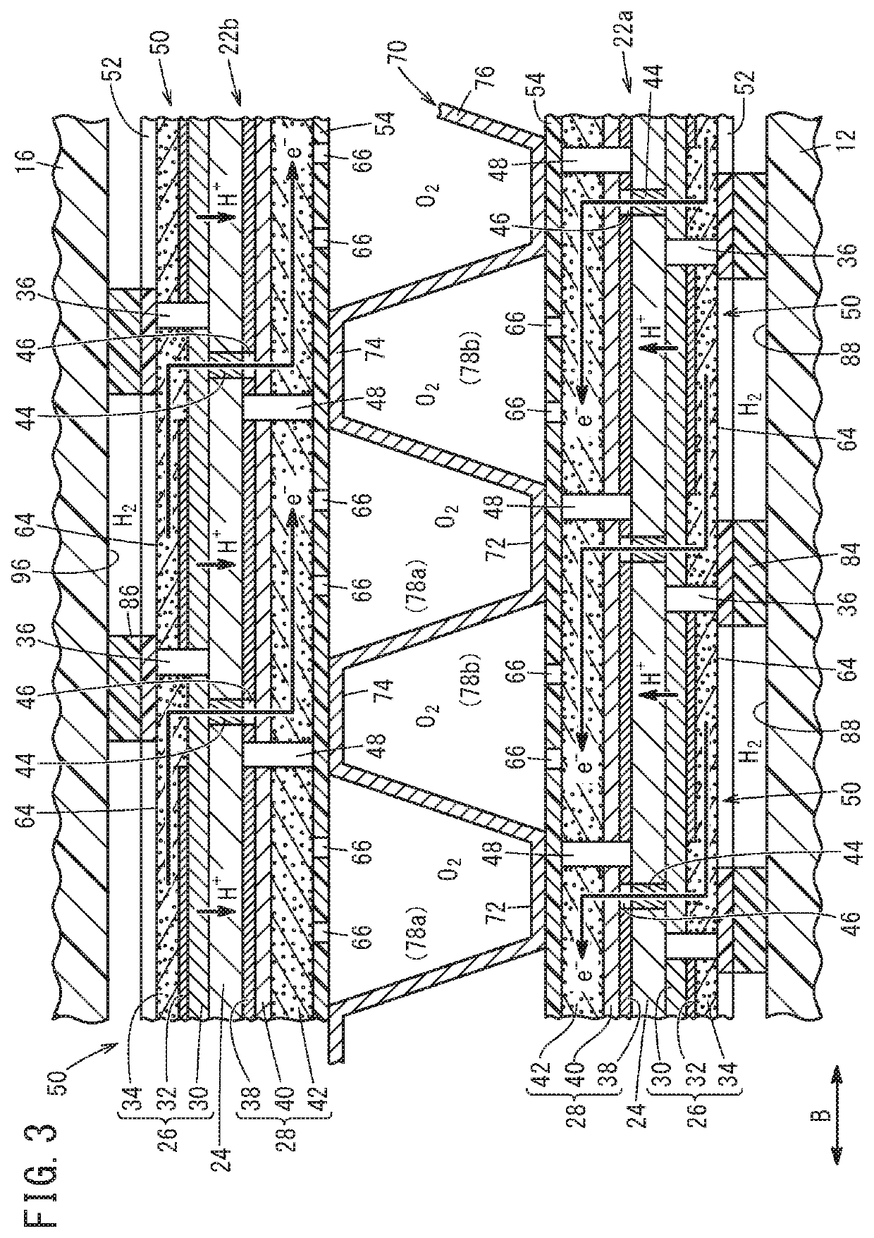
[0024]Hereinafter, a preferred embodiment of the present invention will be described with reference to the accompanying drawings. The following expressions “lower”, “upper”, “left”, and “right” correspond particularly to the lower side, the upper side, the left side, and the right side in FIG. 3. However, these directions are defined for ease of understanding the present invention, and are not intended to define the directions when the fuel cell is used.

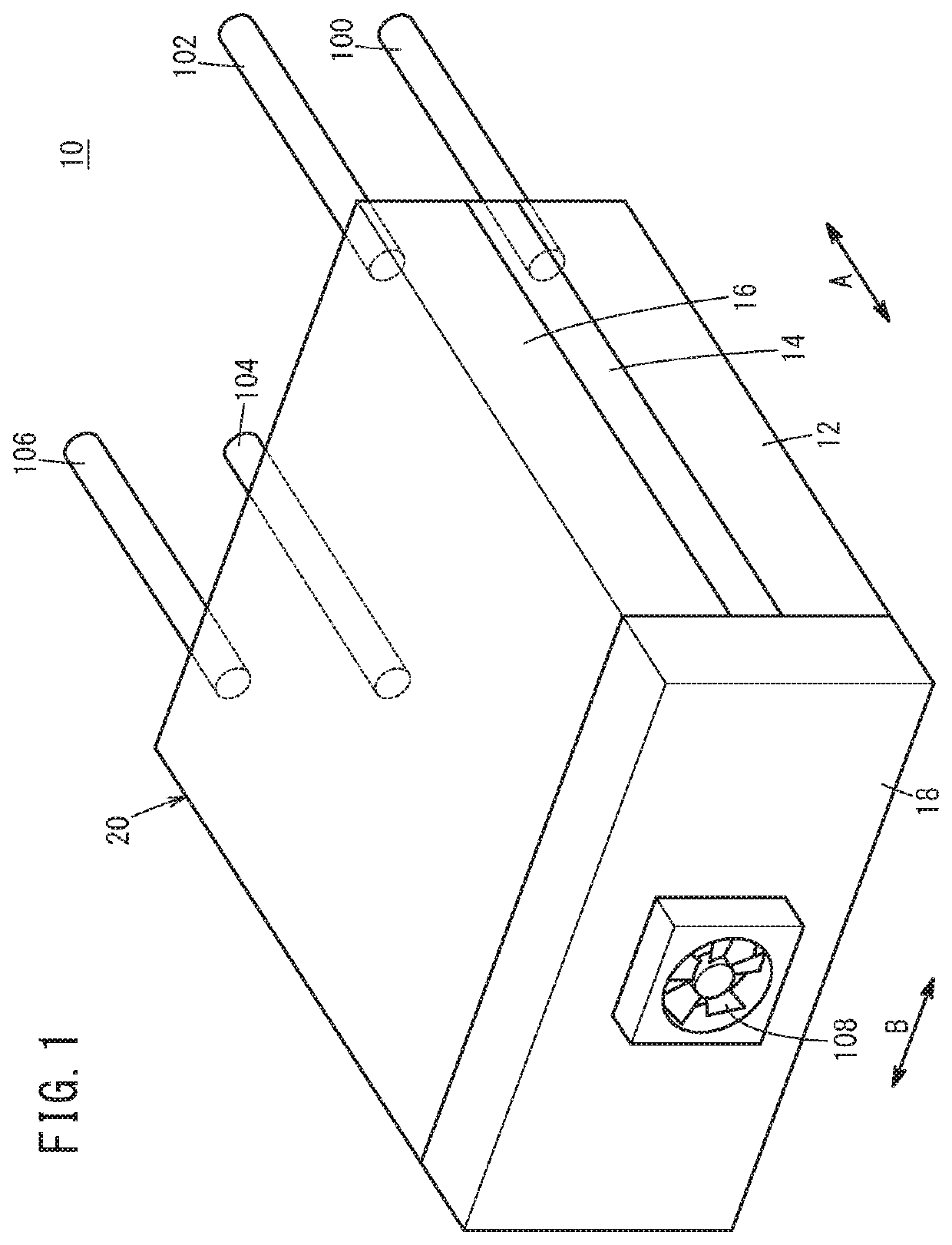
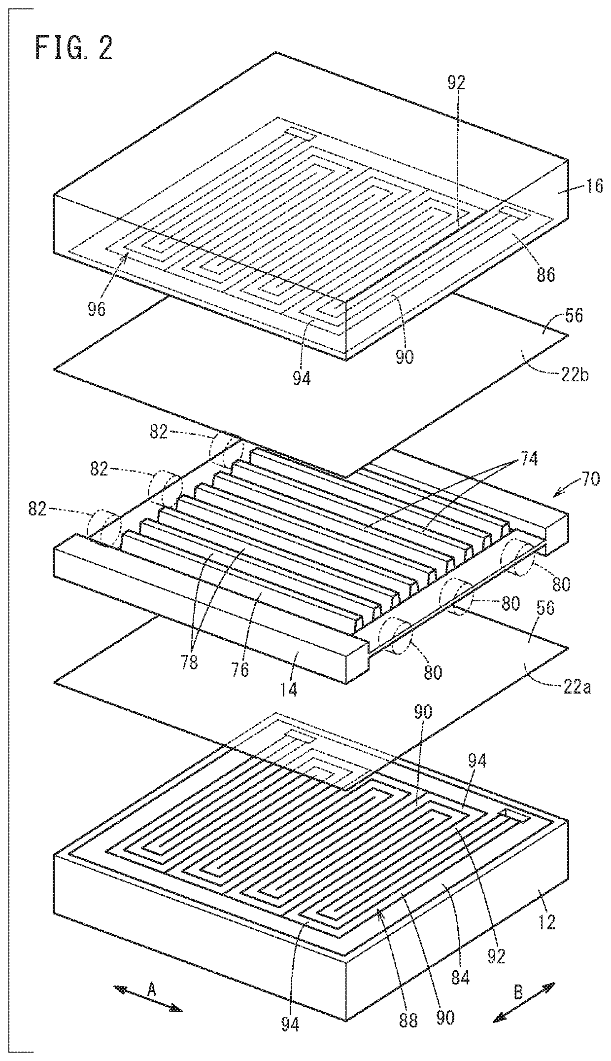
[0025]FIG. 1 is an overall perspective view schematically showing a fuel cell 10 according to the embodiment, FIG. 2 is an exploded perspective view showing main components of the fuel cell 10 according to the embodiment, and FIG. 3 is a vertical cross sectional view showing main components of the fuel cell 10 according to the embodiment. In the fuel cell 10, a lower housing member 12, a support panel 14 of an oxygen-containing gas supply layer 70 described later, an upper housing member 16, and a fan attachment member 18 shown in FI...


PUM

PropertyMeasurementUnit
heat resistanceaaaaaaaaaa
temperatureaaaaaaaaaa
operating temperatureaaaaaaaaaa

Abstract

Electrolyte membrane electrode structures that constitute a fuel cell according to the present invention have a staggered arrangement wherein a part of an anode electrode faces a part of one of two adjacent cathode electrodes, with an electrolyte membrane being interposed therebetween, and another part of the anode electrode faces a part of the other cathode electrode, with an interconnect part being interposed therebetween, said interconnect part being formed in the electrolyte membrane. The electrolyte membrane electrode structures are sealed in a laminate layer which is obtained by bonding an anode-side porous film that covers the anode electrode and a cathode-side porous film that covers the cathode electrodes with each other.

Description

TECHNICAL FIELD[0001]The present invention relates to a fuel cell including a membrane electrode assembly formed by providing a plurality of anodes and a plurality of cathodes for one electrolyte membrane.BACKGROUND ART[0002]A typical fuel cell is formed by stacking a plurality of unit cells together. Each of the unit cells is obtained by sandwiching a membrane electrode assembly (MEA) between a pair of separators. This structure is known as a fuel cell stack. In contrast, in recent years, it is proposed to provide a plurality of anodes and a plurality of cathodes for one electrolyte electrode assembly to form a plurality of unit cells having a planar shape.[0003]As described in Japanese Laid-Open Patent Publication No. 2011-204609, in this case, interconnecting sections are formed in the electrolyte membrane for electrically connecting the adjacent unit cells together. That is, a plurality of unit cells are connected in series through the interconnecting sections. In the case of ad...

Claims


Application Information

Patent Timeline
Patent Type & Authority Applications(United States)
IPC IPC(8): H01M8/1006H01M8/2465
CPCH01M8/1006H01M8/2465H01M8/2418Y02E60/50H01M8/2483H01M8/2484H01M8/0254H01M8/1065H01M8/1004H01M8/0206H01M8/0258H01M8/0239H01M8/0245
Inventor MUGISHIMA, TAKEHIRONAGASAKI, HITOSHIFUJIMOTO, AKIOMIZUNO, AYUMI
Owner HONDA MOTOR CO LTD
Why Eureka
Try Eureka