
Robotic manipulators

a robot and manipulator technology, applied in the field of physical design of a controlled robotic system, can solve the problems of repeating complex performances with unerring precision, difficult to build automated machines for manipulating objects of various shapes, sizes, inertias and materials, and difficult to perform many tasks that involve contact with other objects,

Inactive Publication Date: 2021-02-04
DEXTROUS ROBOTICS INC
View PDF11 Cites 2 Cited by
  • Summary
  • Abstract
  • Description
  • Claims
  • Application Information

AI Technical Summary

Benefits of technology

The patent describes a robotic arm design that uses simple kinematics of movement. It includes a chopstick with at least four degrees of freedom of movement and an electromagnetic actuator for each degree of movement. The arm also has a 6-axis force / torque sensor mounted inline between the actuators and each chopstick. By using this design, the arm can effectively control its movement and apply force in a precise manner.

Problems solved by technology

It is currently very hard to build automated machines for manipulating objects of various shapes, sizes, inertias, and materials.
They lift massive objects, move with blurring speed, and repeat complex performances with unerring precision.
Yet outside of these carefully controlled robot realms, even the most sophisticated robot would be unable to perform many tasks that involve contact with other objects.
As such, outside of controlled environments, robots have only performed sophisticated manipulation tasks when operated by a human.
Outside of controlled settings, however, robots have only performed sophisticated manipulation tasks when operated by a human.
Through teleoperation, even highly complex humanoid robots have performed a variety of challenging everyday manipulation tasks, such as grasping everyday objects, using a power drill, throwing away trash, and retrieving a drink from a refrigerator.
But accurate control of robots that autonomously, physically interact with various objects in their environments has proved elusive.

Method used


Image

  • Robotic manipulators
  • Robotic manipulators
  • Robotic manipulators

Examples


Embodiment Construction

.”

BRIEF DESCRIPTION OF THE DRAWINGS

[0013]Features, aspects, and embodiments are described in conjunction with the attached drawings, in which:

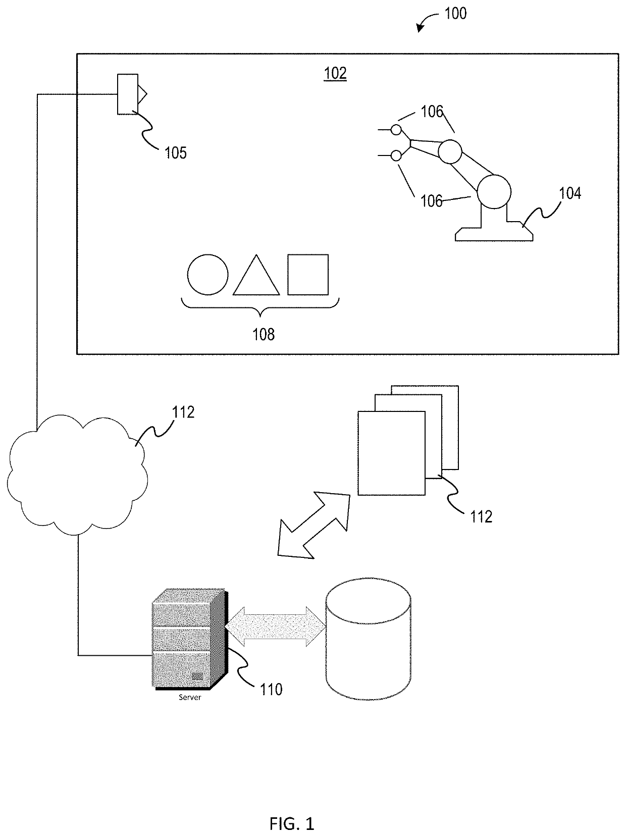
[0014]FIG. 1 is a diagram illustrating an example an environment in which a robot can be controlled in accordance with one embodiment;

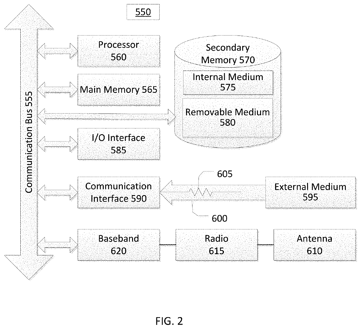
[0015]FIG. 2 is a block diagram illustrating an example wired or wireless system that can be used in connection with various embodiments described herein;

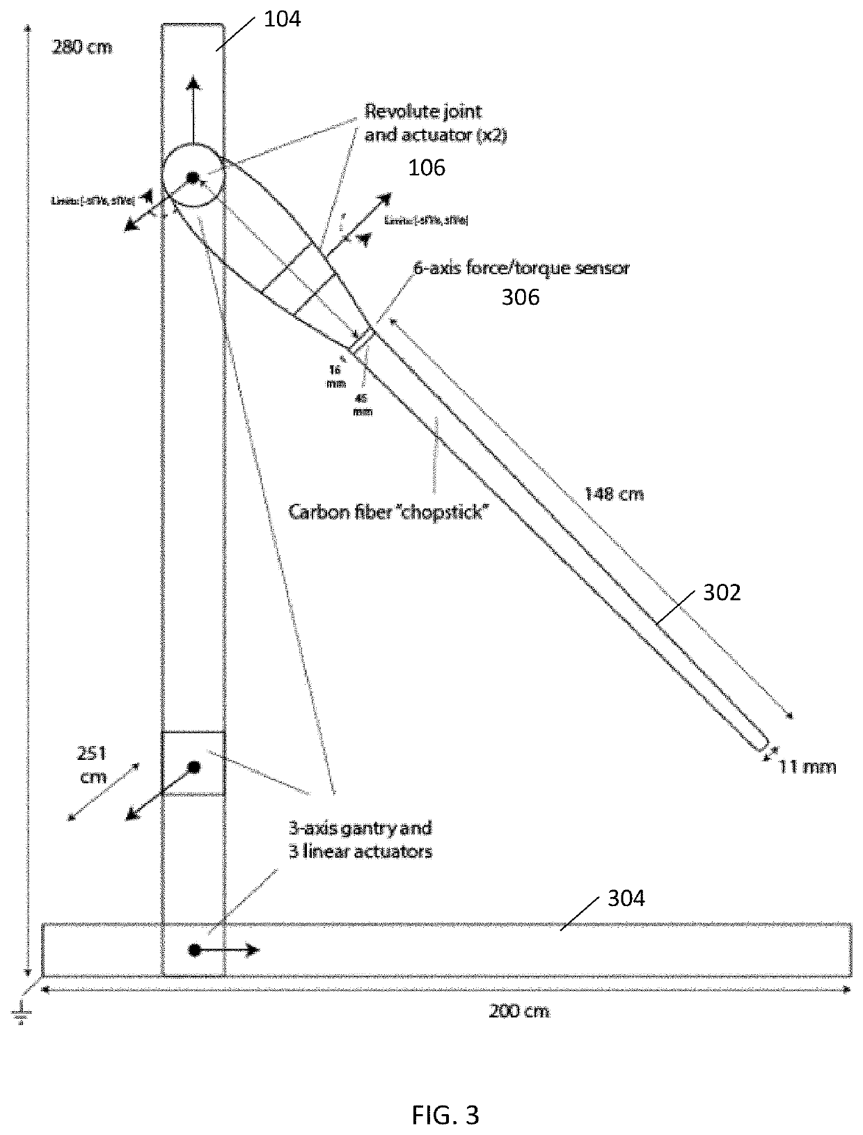
[0016]FIG. 3 is a diagram illustrating an example robot that can be used in the environment of FIG. 1 and controlled in accordance with one embodiment;

[0017]FIGS. 4A and 4B illustrate an example robot mounted on a gantry in accordance with one example embodiment;

[0018]FIGS. 5A and 5B are diagrams illustrating mechanisms that allow each arm of, e.g., the robot of FIGS. 4A and 4B to move up and down a corresponding leg; and

[0019]FIG. 6 is a diagram illustrating a differential chain drive that effects rotational motion at a pulley C, and linear motion of the carri...


PUM


Abstract

A robot comprising a chopstick, configured for at least four degrees of freedom of movement, a stiff body of shape and proportions approximate to a pool cue; an electromagnetic actuator, comprising a motor, for each degree of freedom of movement coupled with the stiff body, wherein the functional mapping from each actuator's motor current to torque output along an axis of motion is stored, and used in concert with a calibrated model of the robot for effective impedance control; and a 6-axis force / torque sensor mounted inline between the actuators and each chopstick.

Description

CROSS-REFERENCE TO RELATED APPLICATIONS[0001]This application claims priority under 35 U.S.C. 119(e) to U.S. Provisional Patent Application No. 62 / 882,395, filed Aug. 2, 2019, U.S. Provisional Patent Application No. 62 / 882,396, filed Aug. 2, 2019 and U.S. Provisional Patent Application No. 62 / 882,397, filed Aug. 2, 2019 the disclosures of which are hereby incorporated herein by reference in their entirety as if set forth in full.[0002]This application is also related to U.S. patent application Ser. No. unassigned, filed on Jul. 30, 2020, entitled SYSTEMS AND METHODS FOR ROBOTIC CONTROL UNDER CONTACT, and is also related to U.S. patent application Ser. No. unassigned, filed on Jul. 30, 2020, entitled ROBOTIC SYSTEM FOR PICKING AND PLACING OBJECTS FROM AND INTO A CONSTRAINED SPACE, all of which are incorporated herein by reference in their entirety as if set forth in full.BACKGROUND1. Technical Field[0003]The embodiments described herein are related to the physical design of a control...

Claims


Application Information

Patent Timeline
Patent Type & Authority Applications(United States)
IPC IPC(8): B25J9/16B25J9/12B25J13/08B25J9/00B25J15/08
CPCB25J9/1694B25J9/12B25J13/087B25J9/046B25J9/0012B25J15/08B25J13/085B25J9/023B25J9/0087B25J13/084G05B2219/39343G05B2219/39346G05B2219/39347G05B2219/39348B25J9/1612B25J9/1682G05B2219/39532G05B2219/39528G05B2219/40627G05B2219/40293G05B2219/40272B25J9/1666B25J9/161B25J9/1697B25J9/1676B25J9/1653B25J13/088B25J9/1664B25J9/1669G05B2219/39536B25J9/1633B25J9/026B65G67/02G05B19/4155G05B2219/50391B25J9/163B25J13/082B25J15/0038B25J15/0233
Inventor DRUMWRIGHT, EVANZAPOLSKY, SAMSCHWANDT, DOUGCORTELL, JASON
Owner DEXTROUS ROBOTICS INC
Learn More