Lift rotor system

a rotor system and rotor technology, applied in the direction of canard-type aircraft, vertical landing/take-off aircraft, transportation and packaging, etc., can solve the problems of aircraft performance compromise, associated penalties in range and/or payload capability, etc., to reduce the amount of lift the rotor can generate, rotate more slowly, and reduce the effect of lifting

Active Publication Date: 2021-02-04
ROLLS ROYCE PLC
View PDF0 Cites 5 Cited by
  • Summary
  • Abstract
  • Description
  • Claims
  • Application Information

AI Technical Summary

Benefits of technology

[0027]In some embodiments, the rotor blades are simple symmetric aerofoils with a maximum thickness at 50% of the chord. This design provides the advantage that the drag created by the external rotor (which protrudes beyond the faring when the rotor is in the stowed position) travelling through the air in the opposite direction compared to when it is rotating to provide lift is reduced.
[0028]In some embodiments, the first and/or second shaft may be provided with further rotor blades in addition to the first and second/third and fourth. Extra blades can increase the amount of lift the rotors can generate, or allow the rotors to rotate more slowly whilst producing the same amount of lift force.
[0029]In some embodiments, each shaft retracts and extends electrically between the extended and retracted positions. The lift rotor arrangement may further comprise a motor or a respective motor (e.g. an electric motor) for retracting and extending each shaft between the extended and retracted positions. The motor(s) may be housed within the fairing. Such an arrangement can be used within all-electric or hybrid VTOL aircraft, reducing the environmental impact of a VTOL using such a lift rotor arrangement.
[0030]In some embodiments, the fairing is

Problems solved by technology

In most of the current VTOL aircraft configurations, the inactive lift rotors can generate significant amounts of drag duri

Method used


Image

  • Lift rotor system
  • Lift rotor system
  • Lift rotor system

Examples


Embodiment Construction

[0048]Aspects and embodiments of the present disclosure will now be discussed with reference to the accompanying figures. Further aspects and embodiments will be apparent to those skilled in the art.

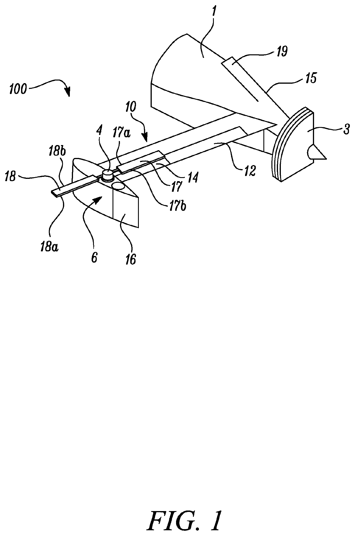
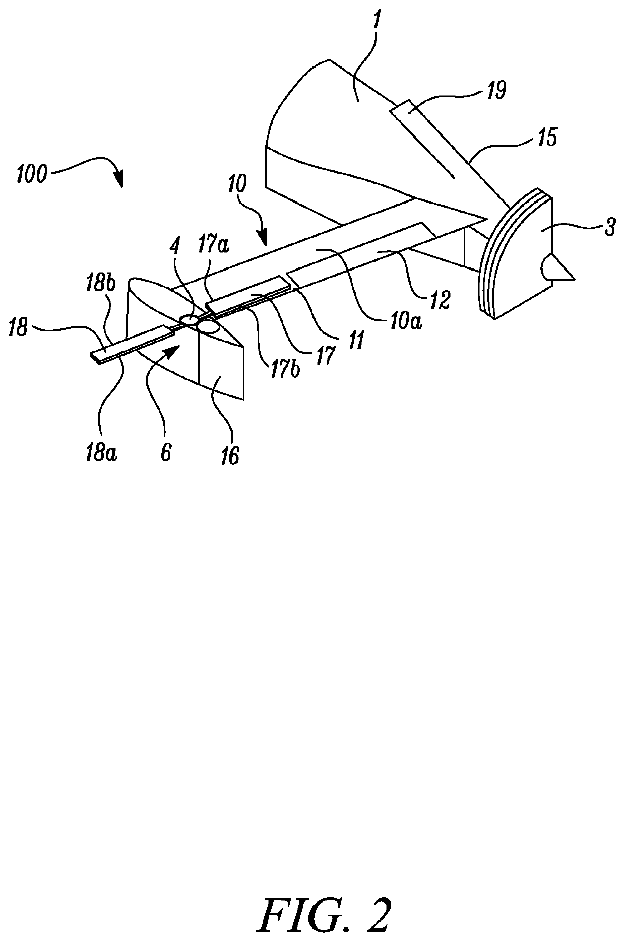
[0049]FIG. 1 shows a first embodiment of a lift rotor arrangement 100 for a VTOL aircraft in the extended position.

[0050]The lift rotor arrangement 100 comprises an aerodynamic fairing 6 mounted on the tip of a wing segment 10. The fairing 6 comprises a rearward rudder portion 16. The lift rotor arrangement also includes a first rotor blade 17 and second rotor blade 18 mounted on a first shaft 4 extending vertically from the fairing 6.

[0051]In the extended position when vertical thrust is required for vertical take-off, the first shaft 4 is vertically extended away from the fairing 6 by an electric motor (not shown) housed within the fairing 6. In this extended position, the first and second blades 17, 18 are spaced away from the wing segment 10 and are free to rotate with the first shaf...


PUM


Abstract

A lift rotor arrangement (100) for a VTOL aircraft (200). The lift rotor arrangement (100) comprises: a fairing (6) mounted on a wing segment (10); and first and second rotor blades (17, 18) mounted on a first shaft (4) extending vertically from the fairing (6). The first shaft (4) is movable between an extended position in which the first and second rotor blades (17, 18) are vertically spaced above the wing segment (10) and are rotatable to provide vertical lift, and a retracted position in which the first and second rotor blades (17, 18) are rotationally-fixed with the first rotor blade (17) stowed within the wing segment (10). The blades (17, 18) may be rotatable around an axis substantially perpendicular to the axis of the respective first shaft (4) so as to act as ailerons/elevons in the retracted position.

Description

CROSS-REFERENCE TO RELATED APPLICATIONS[0001]This specification is based upon and claims the benefit of priority from Greek Patent Application Number 20190100324 filed on 30 Jul. 2019, and from UK Patent Application Number GB1913668.8 filed on 23 Sep. 2019, the entire contents of which are incorporated herein by reference.BACKGROUNDField of the Disclosure[0002]The present disclosure relates to a lift rotor system for a vertical take-off and landing (VTOL) aircraft, and provides an arrangement as set out in the appended claims. It also relates to a wing segment for a VTOL aircraft and a VTOL aircraft having such a lift rotor arrangement and wing segment.Description of the Related Art[0003]Lift-plus-cruise vertical take-off and landing (VTOL) aircraft can operate in both airplane and helicopter modes. Their configuration is based on utilising separate systems for hover lift and cruise thrust. They carry lift rotors which are active during vertical take-off and landing, and cruise roto...

Claims


Application Information

Patent Timeline
IPC IPC(8): B64C27/473B64C29/00B64C7/00B64C39/06B64C9/00
CPCB64C27/473B64C29/0016B64C2009/005B64C39/068B64C9/00B64C7/00B64C11/30B64C27/26B64C11/28B64C29/0025B64C39/12
Inventor PACHIDIS, VASILEIOSSAIAS, CHANA A.
Owner ROLLS ROYCE PLC
Why Eureka
Try Eureka