Power conversion device

Active Publication Date: 2021-02-04
MITSUBISHI ELECTRIC CORP
View PDF0 Cites 1 Cited by
  • Summary
  • Abstract
  • Description
  • Claims
  • Application Information

AI Technical Summary

Benefits of technology

[0014]According to a power conversion device of the present disclosure, circulating current can flow through a DC/DC converter and a coupled reactor between a first smoothing capacitor and a second smoothing capacitor, whereby electric charges stored in the first smoothing capacitor and the second smoothing capacitor can be immediately discharged by copper loss occurring in a path through which current flows, iron loss occurring in the core of the coupled reactor, and loss occurring in the DC/DC converter. Thus, the discharge period of the first smoothing capacitor and the second smoothing capacitor can be shortened in comparison with the conventional case, and accordingly, the backup power supply for driving the DC

Problems solved by technology

In a conventional method of discharging by alternately turning on and off upper and lower arms of an inverter, when

Method used


Image

  • Power conversion device
  • Power conversion device
  • Power conversion device

Examples


Example

Embodiment 2

[0116]A power conversion device according to embodiment 2 of the present disclosure is characterized in that the coupling configuration of the coupled reactor 4 used in embodiment 1 is changed to a cumulative type. The other configurations are the same as the configurations in embodiment 1, and therefore the detailed description thereof is omitted.

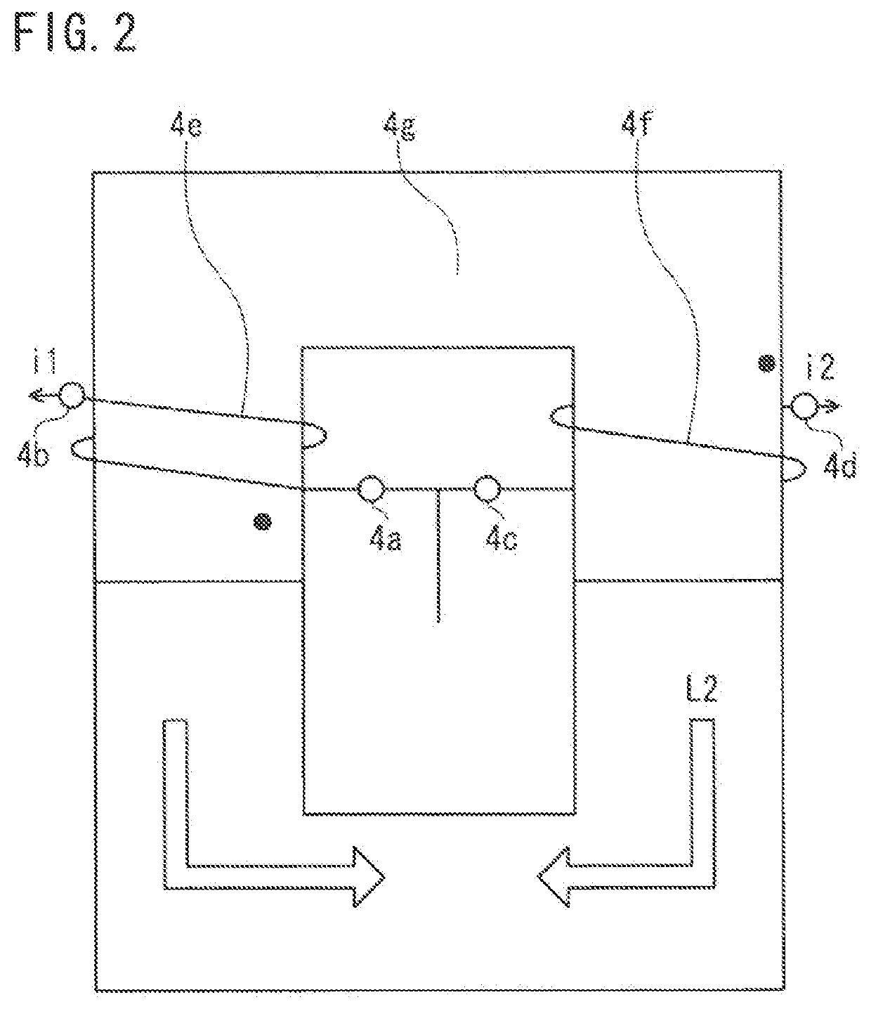
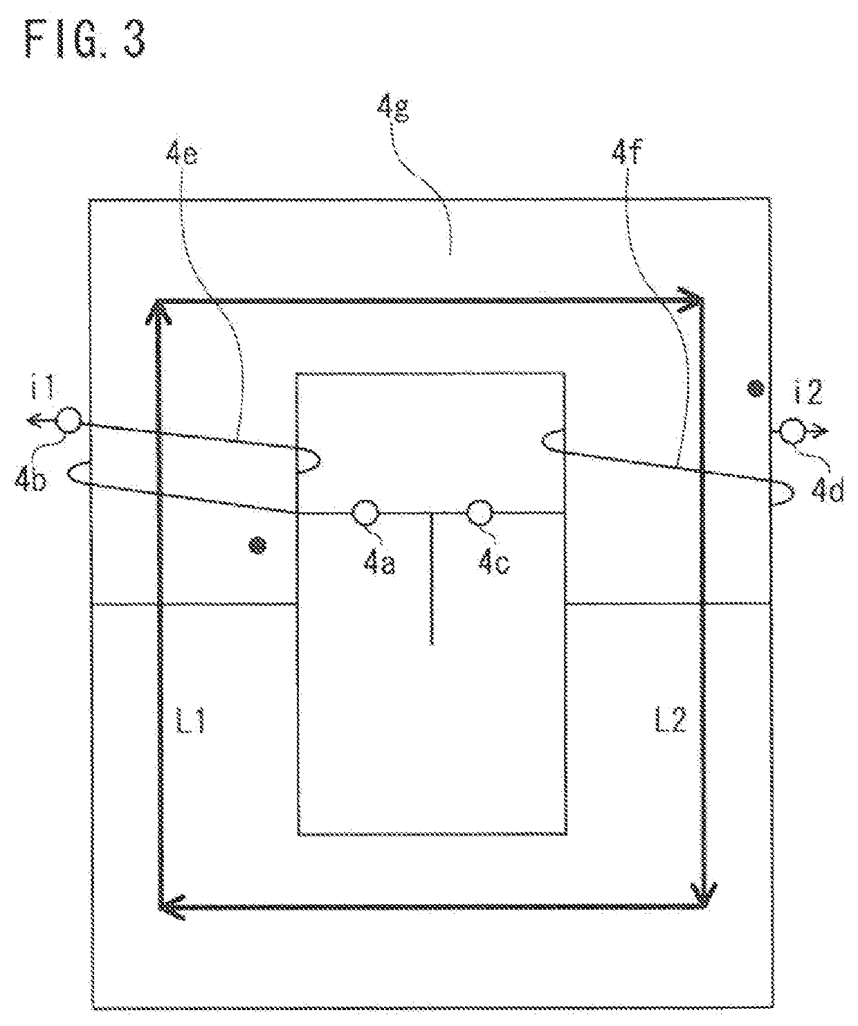
[0117]Here, the cumulative-type coupled reactor 4 refers to a coupled reactor in which the first winding 4e and the second winding 4f are wound so that DC magnetic fluxes generated in the core 4g by the first winding 4e and the second winding 4f are generated in such directions as to strengthen each other when DC current flows through the first winding 4e and the second winding 4f, as shown in FIG. 21.

[0118]FIG. 24 shows the switching timings of the DC / DC converter 5, and changes over time in current at each part and winding currents of the coupled reactor 4, when phase shift operation of the DC / DC converter 5 is performed, usi...


PUM


Abstract

A magnetically coupled reactor and a DC/DC converter are provided between a DC power supply and an inverter. A first smoothing capacitor is provided between the DC power supply and the coupled reactor. A second smoothing capacitor is provided between the DC/DC converter and the inverter. A controller is provided in order to control switching operations of the inverter and the DC/DC converter. The controller causes semiconductor switching elements composing upper and lower arms of the DC/DC converter to perform complementary operations so as to be alternately turned on/off, and causes left and right legs to operate with their switching phases shifted from each other, thereby electric charges stored in both smoothing capacitors are discharged by energy loss in the coupled reactor and the DC/DC converter.

Description

TECHNICAL FIELD[0001]The present disclosure relates to a power conversion device mounted on an electric vehicle, for example.BACKGROUND ART[0002]Conventionally, there has been known an electric vehicle including a DC power supply capable of charging and discharging, a boost converter for boosting DC voltage supplied from the DC power supply, a first smoothing capacitor for smoothing voltage between the DC power supply and the boost converter, an inverter for converting high DC voltage outputted from the boost converter to AC voltage, a second smoothing capacitor for smoothing voltage between the boost converter and the inverter, and a three-phase AC electric motor to which the AC voltage outputted from the inverter is applied, whereby a driving force and a braking force of the vehicle are controlled.[0003]In such an electric vehicle, in order to ensure safety of the vehicle, it is necessary to immediately discharge high-voltage electric charge stored in a smoothing capacitor when th...

Claims


Application Information

Patent Timeline
IPC IPC(8): H02M3/158
CPCH02M3/1584H02M2003/1586H02M1/0064H02M1/322H02M3/1586H02M3/003
Inventor MURAKAMI, SATOSHIIWABUKI, HIROYASUTAKESHIMA, YOSHIHIRO
Owner MITSUBISHI ELECTRIC CORP
Why Eureka
Try Eureka