

Camera module
a camera module and camera technology, applied in the field of camera modules, can solve the problems of increasing the overall size of the conventional camera module, high power consumption of the lens-moving apparatus, etc., and achieve the effect of reducing the size of the main board (or the camera module) according to embodiments, improving tolerance, and reducing the size of the main board
Pending Publication Date: 2021-02-18
LG INNOTEK CO LTD
View PDF0 Cites 6 Cited by
- Summary
- Abstract
- Description
- Claims
- Application Information
AI Technical Summary
Benefits of technology
The camera module described in this patent has several technical effects. First, by using a base and two flexible printed circuit boards to connect the main board and liquid lens, the tolerance at the contact points between the components is improved, ensuring reliable electrical connection. Second, the size of the main board or camera module may be reduced, as the first and second connection substrates do not need to be bent to connect to the main board. Third, the reliability of the first and second connection substrates is increased as they are inhibited from being disconnected or separated from other components. Fourth, the design constraints of the first and second connection substrates are relaxed, allowing for more design flexibility. Fifth, the supply of driving voltage to the liquid lens is facilitated during active alignment, improving the reliability of the camera module.
Problems solved by technology
However, the lens-moving apparatus has high power consumption, and an additional cover glass needs to be provided separately from a camera module in order to protect the lens-moving apparatus, thus causing a problem in that the overall size of the conventional camera module increases.
Method used
View moreImage
Smart ImageViewing Examples

Examples
Embodiment Construction
[0390]Various embodiments have been described in the best mode for carrying out the disclosure.
INDUSTRIAL APPLICABILITY
[0391]A camera module according to embodiments may be used in camera / video devices, telescopic devices, microscopic devices, an interferometer, a photometer, a polarimeter, a spectrometer, a reflectometer, an auto-collimator, a lens-meter, a smartphone, a laptop computer, a tablet computer, etc.
Login to View More PUM
 Abstract
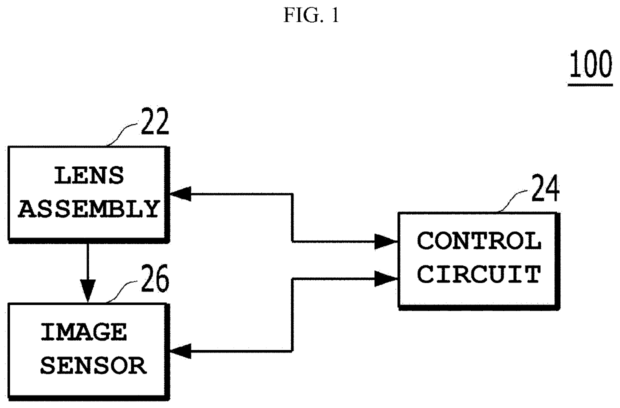
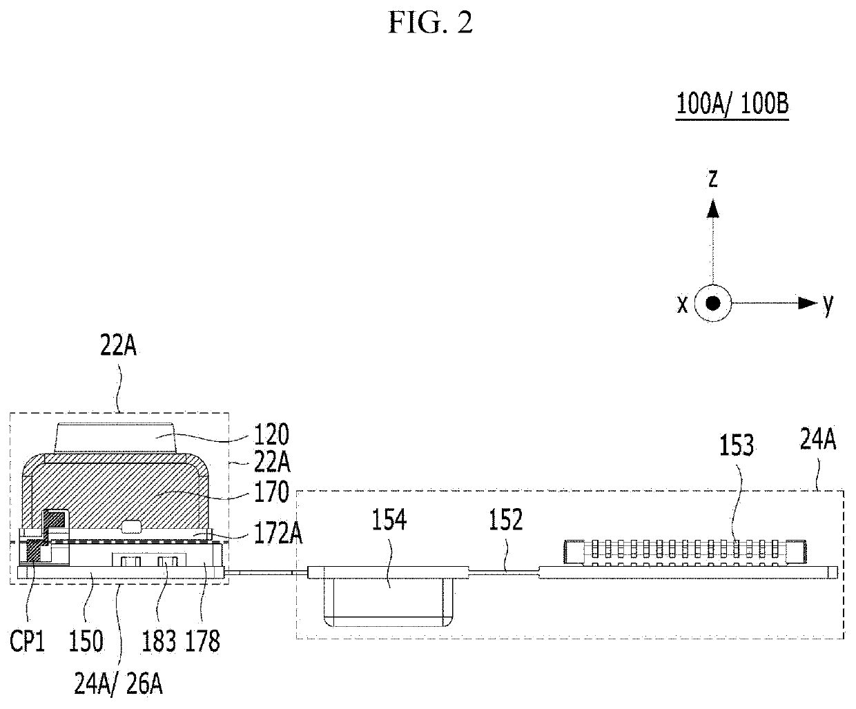
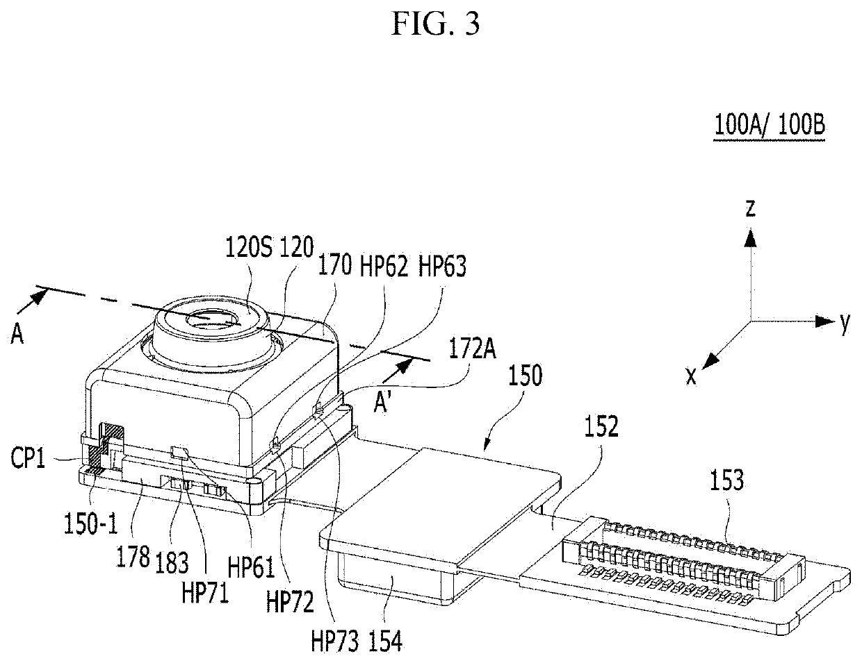
A camera module includes a liquid lens unit, a lens holder in which the liquid lens unit is disposed, a main board configured to supply a driving signal to drive the liquid lens unit, and a base disposed between the liquid lens unit and the main board, the base being configured to transmit the driving signal output from the main board to the liquid lens unit, wherein the base includes a body in which the lens holder is disposed, a first pillar and a second pillar protruding upwards from the body, and a first connection part and a second connection part electrically connecting the liquid lens unit to the main board.
Description
CROSS-REFERENCE TO RELATED APPLICATIONS[0001]This application is the U.S. national stage application of International Patent Application No. PCT / KR2019 / 000936, filed Jan. 23, 2019, which claims the benefit under 35 U.S.C. § 119 of Korean Patent Application No. 10-2018-0010622, filed Jan. 29, 2018, the disclosures of each of which are incorporated herein by reference in their entirety.TECHNICAL FIELD[0002]Embodiments relate to a camera module.BACKGROUND ART[0003]People who use portable devices demand optical devices that have high resolution, are small, and have various photographing functions. For example, these various photographing functions may be at least one of an optical zoom-in / zoom-out function, an auto-focusing (AF) function, or a hand-tremor compensation or optical image stabilizer (OIS) function.[0004]In a conventional art, in order to implement the above-described various photographing functions, a method of combining a plurality of lenses and directly moving the combine...
Claims
Login to View More Application Information
Patent Timeline
 Patent Type & AuthorityApplications(United States)
IPC IPC(8): G02B3/14G02B7/04G03B17/12H04N5/225H05K1/14
CPCG02B3/14G02B7/04H05K1/141H04N5/2254G03B17/12G02B7/08G02B13/14G02B27/646H05K2201/10151H05K2201/10606H05K3/341H05K2201/10272G03B30/00G03B3/10G03B2205/0084Y02P70/50H04N23/57H04N23/55H04N23/54G03B5/00G03B2205/0007
InventorKIM, DONG HYUN
OwnerLG INNOTEK CO LTD