Check patentability & draft patents in minutes with Patsnap Eureka AI!

Ultrasound guidance dynamic mode switching

a dynamic mode and guidance technology, applied in the field of ultrasonic imaging, can solve the problems of inability to accurately determine the position of the target organ

Pending Publication Date: 2021-02-25
CAPTION HEALTH INC
View PDF1 Cites 3 Cited by
  • Summary
  • Abstract
  • Description
  • Claims
  • Application Information

AI Technical Summary

Benefits of technology

The present invention provides a novel and non-obvious method for ultrasound guidance dynamic mode switching. This method involves selecting a predetermined ultrasound diagnostic procedure, identifying an operating mode of the ultrasound diagnostic computing system for a first sequence of views stored in the system's memory as a workflow, placing the ultrasound diagnostic probe in the identified operating mode and acquiring imagery of a target organ utilizing the probe in association with the views of the first sequence of the workflow. The method also includes detecting a feature of the target organ mapped to a different operating mode of the ultrasound diagnostic computing system, identifying a measurement to be performed based upon the detected feature, and recommending a different operating mode to perform the measurement. The invention provides a more efficient and effective method for ultrasound guidance dynamic mode switching, improving the accuracy and reliability of ultrasound imaging procedures.

Problems solved by technology

Even still, ultrasound imagery is not without challenge.
For example, in some instances, an attempted view of a target organ may be incomplete omitting key features of the target organ from the view due to anatomical limitations or an improper placement of the imaging sensor.
As well, external factors such as the anatomical features of the body may inhibit clarity of key features of the target organ despite proper placement of the imaging sensor.

Method used


Image

  • Ultrasound guidance dynamic mode switching
  • Ultrasound guidance dynamic mode switching

Examples


Embodiment Construction

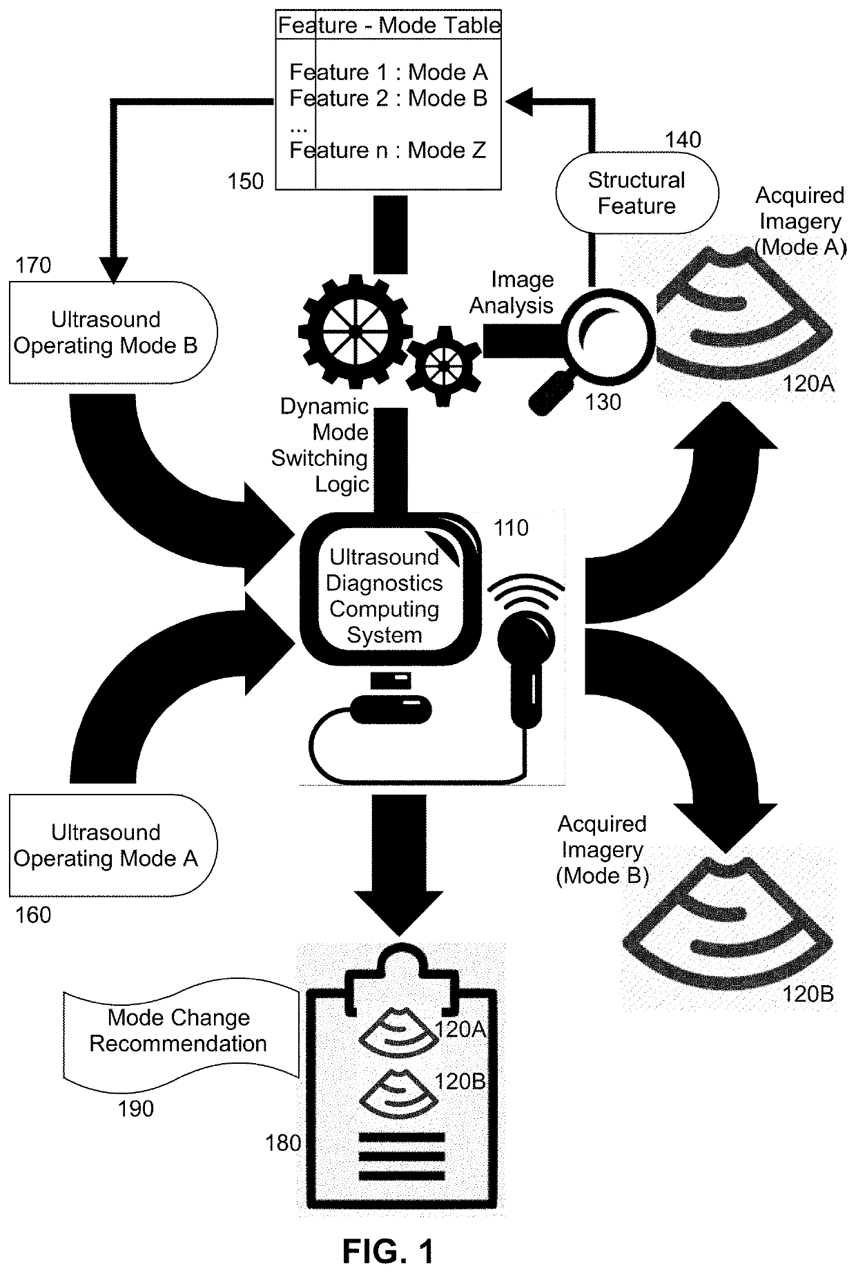
[0020]Embodiments of the invention provide for ultrasound guidance dynamic mode switching. In accordance with an embodiment of the invention, an ultrasound diagnostic computing system is placed into a first operating mode in which imagery of a target organ is acquired according to a sequence of views in a workflow. During the acquisition of the imagery, a feature may be detected within the acquired imagery. The feature is then mapped to a different operating mode of the ultrasound diagnostic computing system. As such, in response to the detection of the feature, a recommendation is displayed in the ultrasound diagnostics computing system to change the operating mode of the ultrasound diagnostics computing system to the different operating mode mapped to the feature, including changing a transducer used in connection with the acquisition of ultrasound imagery. Then, the ultrasound diagnostic computing system is placed into the different operating mode and additional imagery of the ta...


PUM


Abstract

An ultrasound guidance dynamic mode switching method includes selecting a predetermined ultrasound diagnostic procedure in memory of an ultrasound diagnostic computing system and identifying an operating mode of the system for a first sequence of views stored in the memory as a workflow in correspondence to the selected procedure. The method additionally includes placing the system in the identified operating mode and acquiring imagery of a target organ in association with the views of the first sequence of the workflow. Finally, the method includes detecting in the acquired imagery, a feature of the target organ mapped to a different operating mode, and in response to the detection, displaying a recommendation in a display to change operating modes, placing the system into the different operating mode, and acquiring additional imagery of the target organ utilizing the system in association with a different sequence of additional views of a different workflow.

Description

BACKGROUND OF THE INVENTIONField of the Invention[0001]The present invention relates to ultrasound imaging and more particularly to ultrasound image acquisition.Description of the Related Art[0002]Medical imaging refers to the process of creating a visual representation of an interior portion of a mammalian body for the purpose of clinical analysis and medical intervention. Medical imaging seeks to reveal internal structures hidden by the exterior of the body so as to facilitate the diagnosis and treatment of disease. Medical imaging incorporates several different image acquisition methodologies and corresponding radiological devices technologies. Common techniques include X-ray radiography including computerized tomography (CT), magnetic resonance imaging (MRI), medical ultrasonography or ultrasound, endoscopy, elastography, tactile imaging, thermography, medical photography and nuclear medicine functional imaging techniques as positron emission tomography (PET) and Single-photon e...

Claims


Application Information

Patent Timeline
Patent Type & Authority Applications(United States)
IPC IPC(8): A61B8/00A61B8/08
CPCA61B8/54A61B8/465A61B8/13A61B8/0883A61B8/463A61B8/467A61B8/483A61B8/488A61B8/469A61B8/5223
Inventor CADIEU, CHARLESCANNON, MICHAEL G.CHAUDHRY, ALIHONG, HAKOEPSELL, KILIANPARAJULI, NRIPESHPOILVERT, NICOLAS
Owner CAPTION HEALTH INC
Features
  • R&D
  • Intellectual Property
  • Life Sciences
  • Materials
  • Tech Scout
  • Unparalleled Data Quality
  • Higher Quality Content
  • 60% Fewer Hallucinations
Learn More