
Ultrasonic diagnosis system and strain distribution display method

a diagnostic system and ultrasonic technology, applied in the field of ultrasonic diagnosis system and strain distribution display method, can solve the problems of inability to realize real-time calculation and great calculation time, and achieve the effects of high precision, stable computation of elastic modulus distribution, and sufficient uniformity

Active Publication Date: 2006-03-09
SHIINA TSUYOSHI +1
View PDF7 Cites 42 Cited by
  • Summary
  • Abstract
  • Description
  • Claims
  • Application Information

AI Technical Summary

Benefits of technology

[0008] As descried above, with the ultrasonic diagnosis system according to the present invention, the displacement of each measurement point is calculated based upon the correlation between the properties such as the envelope signals with and without application of pressure, thereby enabling real-time estimation of the displacement distribution. Furthermore, with the ultrasonic diagnosis system according to the present invention, the position of each measurement point may be obtained so as to exhibit the maximum correlation coefficient between the envelope signals with and without application of pressure for the measurement points by varying said measurement points in said ultrasonic beam direction at a pitch half the wavelength of said ultrasonic signals, thereby solving a problem of aliasing which is the disadvantage in the Doppler method.
[0010] Accordingly, with the ultrasonic diagnosis system according to the present invention, first, the autocorrelation functions of the envelope signals with and without application of pressure are preferably calculated. Then, the correlation coefficient is obtained by varying the phase difference between the autocorrelation functions thus obtained corresponding to the predetermined variation of the measurement points, e.g., by varying the phase difference thereof at a pitch half the wavelength of the ultrasonic signals. This reduces calculation time for displacement computation, thereby enabling high-speed processing Furthermore, the ultrasonic diagnosis system according to the present invention may further include: storage means for storing the envelope signals of the quadrature-detected RF signals; correlation computing means for calculating the position of each measurement point which exhibits the maximum correlation coefficient between the envelope signals with and without application of pressure for the measurement points surrounded by a two-dimensional correlation window; and displacement computing means for obtaining at least two-dimensional displacement of each measurement point due to application of pressure based upon the position of each measurement point which exhibits the correlation coefficient and the phase difference thus obtained by the correlation computing means.
[0011] That is to say, the method which is referred to as “Combined Autocorrelation method (CA method)” is proposed in the present specification. As described above, the Combined Autocorrelation method has the advantages of two-dimensional and three-dimensional displacement measurement in the spatial correlation method with a correlation window, and the advantage of real-time and high-precision calculation in the Doppler method. The Combined Autocorrelation method allows the user to estimate the displacement distribution regardless of the displacement in the horizontal direction to a certain degree. In this case, the two-dimensional directions may comprise the ultrasonic-beam direction where the ultrasonic signals are received with the ultrasonic probe and the ultrasonic-beam scanning direction. Furthermore, with the ultrasonic diagnosis system according to the present invention, the position of each measurement point which exhibits the maximum correlation coefficient is preferably obtained by varying the measurement points in the ultrasonic-beam direction at a pitch of half the wavelength of the ultrasonic signals, and in the ultrasonic-beam scanning direction at the ultrasonic-beam pitch. Note that while the pitch at which the measurement points are varied in the ultrasonic-beam direction according to the present invention is not restricted to half of the wavelength of the ultrasonic signals, a pitch smaller than half of the wavelength of the ultrasonic signals is preferably employed.
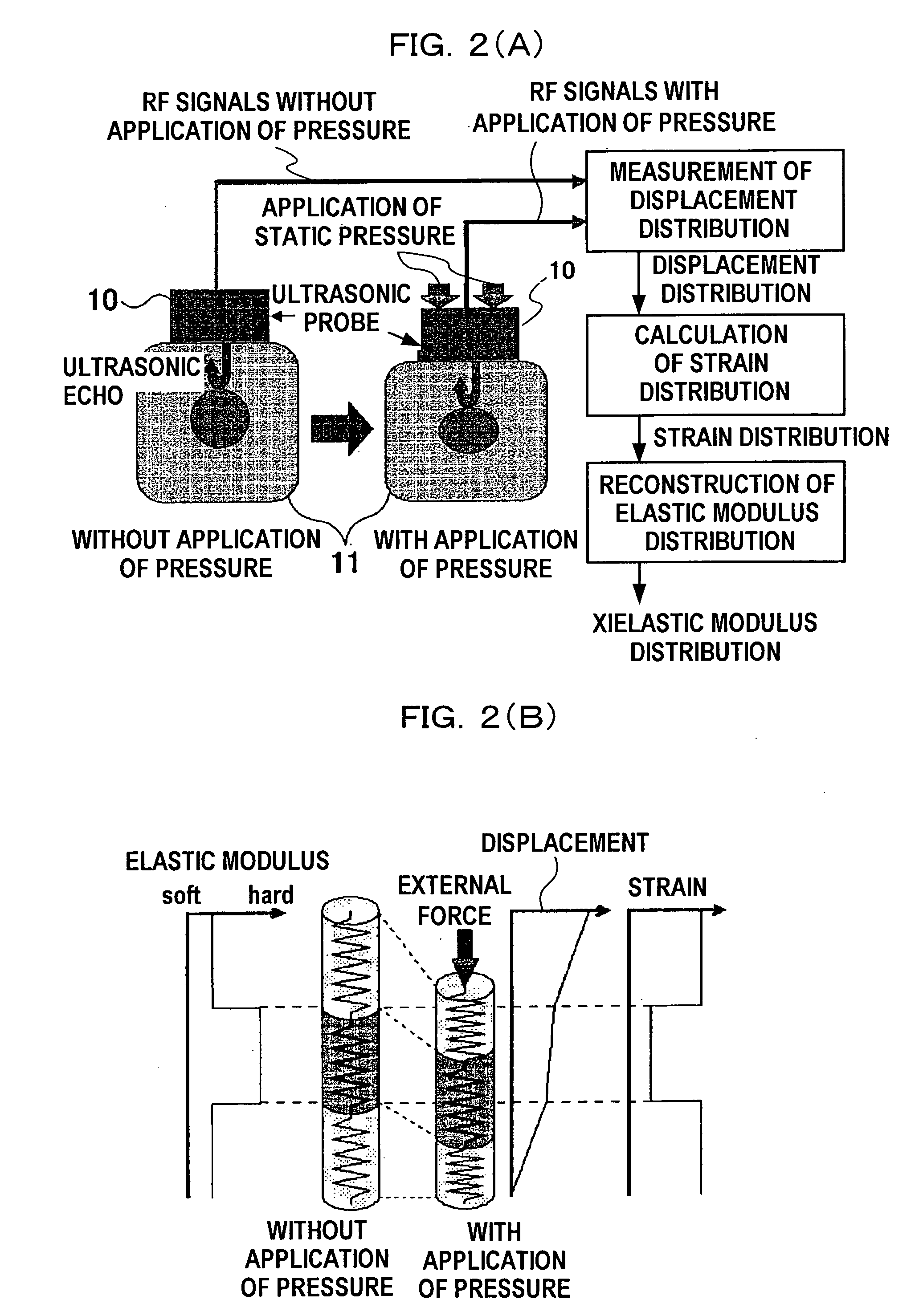
[0015] As described above, calculation according to the present invention is made on the assumption that the tissue exhibits isotropic elasticity. The reason is that the relation between the stress and strain exhibits near-linearity under static external pressure applied to the tissue. Accordingly, approximate calculation can be made on the assumption that the tissue serves as an elastic model. In addition, the tissue exhibits isotropic properties, and accordingly, calculation according to the present invention may be made on the assumption that the tissue serves as an isotropic elastic model. On the other hand, with the present invention, calculation is made on the assumption that the tissue exhibits near-incompressibility. The reason is that if calculation is made on the assumption that the tissue exhibits the complete incompressibility, i.e., calculation is made with the constant Poisson's ratio of 0.5 within the tissue, the elastic equation becomes a special case, leading to a problem that calculation cannot be made using the finite element method. Note that with the present invention, calculation may be made with a uniform Poisson's ratio within the tissue. In this case, only the Young's modulus should be estimated for estimation of the elastic modulus distribution, thereby reducing the inverse problem. Note that the Poisson's ratio exhibits sufficient uniformity within the tissue, and accordingly, with the present invention, calculation is preferably made with the Poisson's ratio of 0.49. The elastic modulus distribution computation according to the present invention enables reconstruction of the elastic modulus distribution based upon the strain distribution in the axial direction alone which can be computed with high precision, thereby enabling stable computation of the elastic modulus distribution.

Problems solved by technology

Note that the correlation computation wherein the position of each measurement point is calculated so as to exhibit the maximum correlation coefficient between the envelope signals with and without application of pressure for the measurement points by varying the phase of the envelope signals with application of pressure along the time axis so as to obtain the autocorrelation function of the envelope signals with application of pressure for each measurement point leads to great calculation time, often leading to a problem that real-time calculation cannot be made.

Method used


Image

  • Ultrasonic diagnosis system and strain distribution display method
  • Ultrasonic diagnosis system and strain distribution display method
  • Ultrasonic diagnosis system and strain distribution display method

Examples


Embodiment Construction

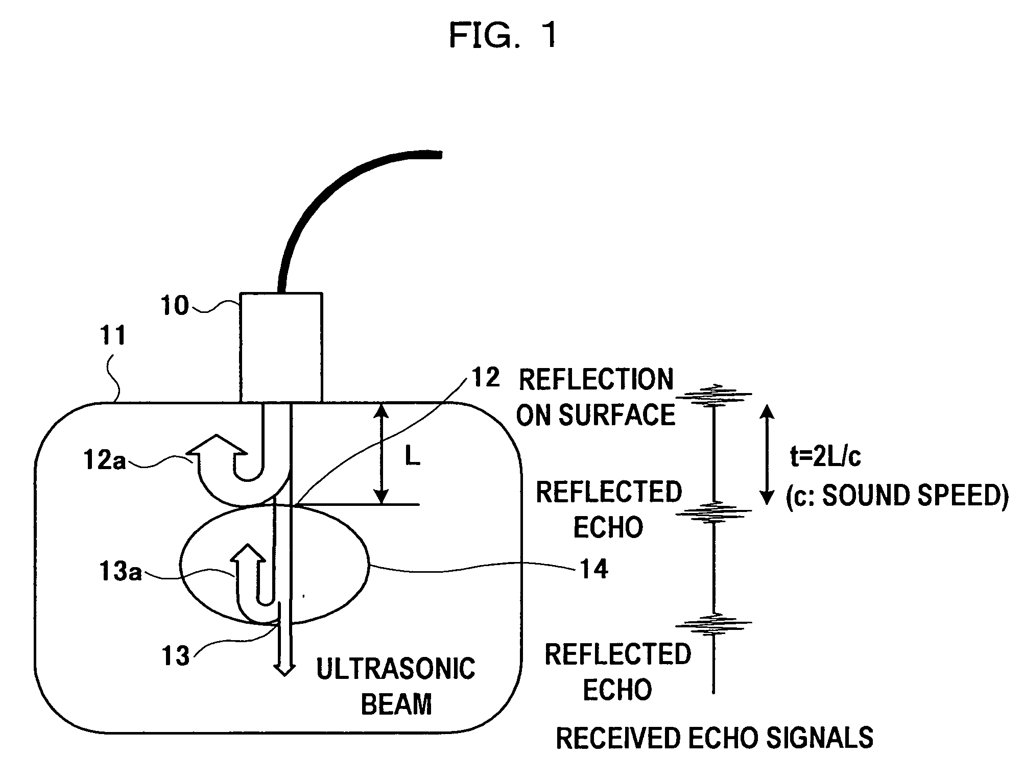
[0043] Description will be made below regarding an ultrasonic diagnosis system according to an embodiment of the present invention with reference to the accompanying drawings. An ultrasonic diagnosis system according to the present embodiment employs a method which is referred to as “expanded combined autocorrelation method” wherein the processing for one-dimensional detection by correlation calculation based upon the envelope signals using the combined autocorrelation method through a one-dimensional window is expanded to handle the displacement in the horizontal direction by two-dimensional detection through a two-dimensional correlation window. Furthermore, with the expanded combined autocorrelation method according to the present embodiment, envelope-correlation calculation is performed for only the grid points set with a pitch of half the wavelength of the ultrasonic wave in the axial direction, and with the beam-line pitch in the horizontal direction for reduction of calculati...


PUM


Abstract

An ultrasonic diagnosis system and strain distribution display method utilizing an ultrasonic probe for performing transmission / reception of ultrasonic signals to / from a subject, a storage arrangement for storing the properties of signals detected with the ultrasonic probe, a correlation computer for calculating a correlation coefficient between the properties with and without pressure applied to the subject, and a phase difference between the received signals with and without application of pressure, based upon the properties stored in the storage arrangement with and without pressure applied to the subject, a computer for calculating a displacement of each measurement point, and a strain distribution of tissue of the subject due to application of pressure, based upon the correlation coefficient and phase difference calculated by the correlation computer, and a display for displaying the strain distribution.

Description

TECHNICAL FIELD [0001] The present invention relates to an ultrasonic diagnosis system and a strain distribution display method which allow the user to make quantitative measurement of the rigidity of the tissue using an ultrasonic diagnosis apparatus. BACKGROUND ART [0002] Ultrasonic diagnosis is applied not only to observation of the tissue structure but also to the field (ultrasonic tissue characterization) where physical quantities within the tissue such as the sound speed, the damping coefficient, and so forth, are measured and furthermore, diagnosis images are created based upon the physical quantities thus measured. As a part of the field, the field is known wherein the rigidity of the tissue, i.e., the elastic property is measured. The aforementioned field is being intensely studied since the elastic property of the tissue has close relation to the pathological situation. For example, it is known that the tissue affected by: sclerosing tumors such as mammary cancer, thyroid ...

Claims


Application Information

Patent Timeline
IPC IPC(8): A61B8/00A61B8/08G01S15/10G01S15/88G01S15/89
CPCA61B5/0048A61B8/08A61B8/0825A61B8/485A61B8/488G01S7/52042G01S15/10G01S15/88G01S15/8906
Inventor SHIINA, TSUYOSHIYAMAKAWA, MAKOTONITTA, NAOTAKA
Owner SHIINA TSUYOSHI
Learn More