
Method for monitoring chatter in machining process

a technology of intelligent manufacturing and monitoring method, applied in the direction of vibration measurement in solids, manufacturing tools, instruments, etc., can solve the problems of reducing the machining precision of workpieces, fatigue damage to tools, and affecting the quality of workpieces, so as to improve the real-time monitoring capability of the system, improve the effect of computation complexity and high speed

Active Publication Date: 2021-03-04
SHENZHEN GRADUATE SCHOOL TSINGHUA UNIV
View PDF0 Cites 4 Cited by
  • Summary
  • Abstract
  • Description
  • Claims
  • Application Information

AI Technical Summary

Benefits of technology

The present invention provides a method for monitoring chatter in the machining process with high efficiency and accuracy. The method uses a fractal algorithm to calculate the dimensions of data segments in the sliding window and compares them to chatter thresholds to determine if chatter occurs. This method has low computation complexity, high speed, and can effectively identify chatter phenomena, including milling, turning, grinding, and the like, with 98% accuracy. It does not require preprocessing and can be used for online monitoring in real-time. Overall, the method improves the efficiency and accuracy of chatter identification, which is important for promoting the development of intelligent monitoring technologies in the machining process.

Problems solved by technology

Chatter is spontaneous oscillation between a tool and a workpiece, which is a main factor affecting machining stability and quality of machined parts.
The occurrence of chatter may reduce the machining precision of workpieces and cause fatigue damage to tools.
These decomposition algorithms are complicated in calculation and need to occupy a large amount of computing resources, which leads to identification lag and difficulty in implementing real-time online chatter monitoring.

Method used


Image

  • Method for monitoring chatter in machining process
  • Method for monitoring chatter in machining process
  • Method for monitoring chatter in machining process

Examples


embodiment 1

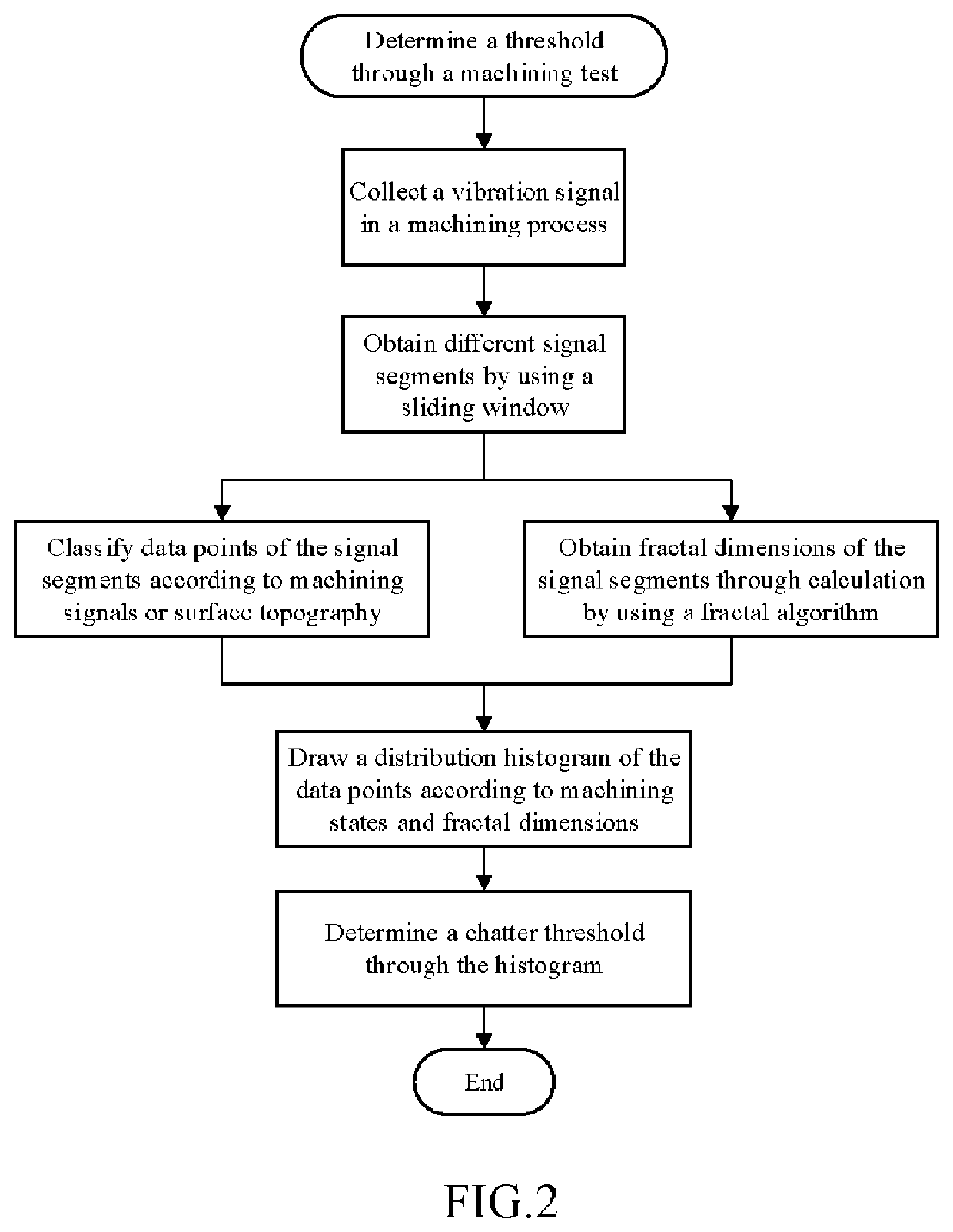
[0067]A threshold of the fractal dimension is an important criterion for determining whether chatter occurs. In this embodiment, a case of determining the threshold by using a histogram is described. With reference to FIG. 2, an implementation of determining the threshold in the present invention is described in details below, including the following steps.

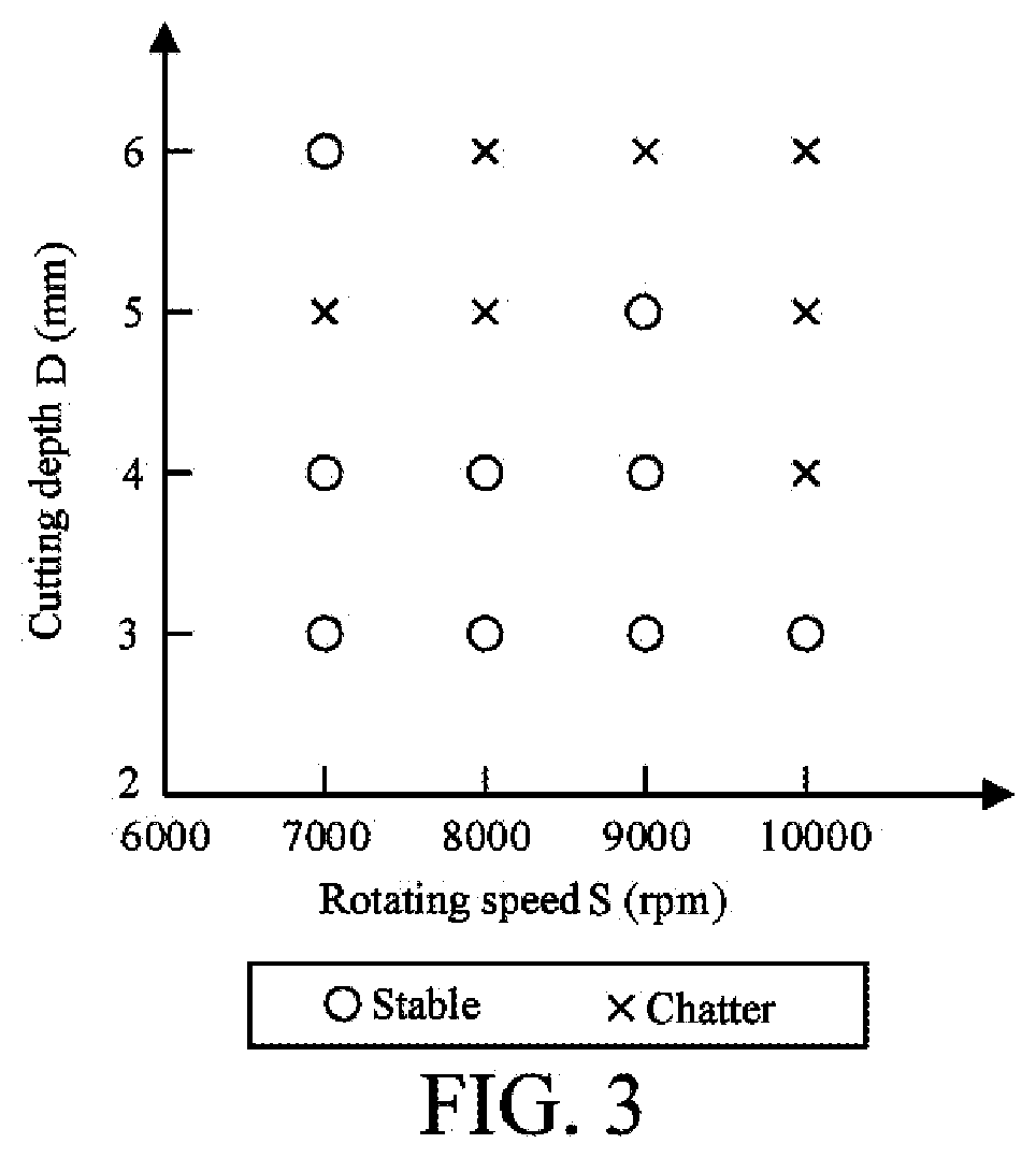
[0068]Step 1: performing a cutting test, and place a vibration sensor on an end of a machine tool spindle. A signal collection device sends the collected vibration signal to a computer. The cutting speeds are 7000 rpm, 8000 rpm, 9000 rpm, and 10,000 rpm. The cutting depths are 3 mm, 4 mm, 5 mm, and 6 mm. An aluminium plate of 100 mm×100 mm is cut, and a total of 16 sets of experimental data are obtained. Chatter occurs in 7 sets, as specifically shown in FIG. 3.

[0069]Step 2: a sliding window model is shown in FIG. 4, with a fixed window size of 800 data points and a step-length of 1 to obtain a fixed-length signal segment for frac...

embodiment 2

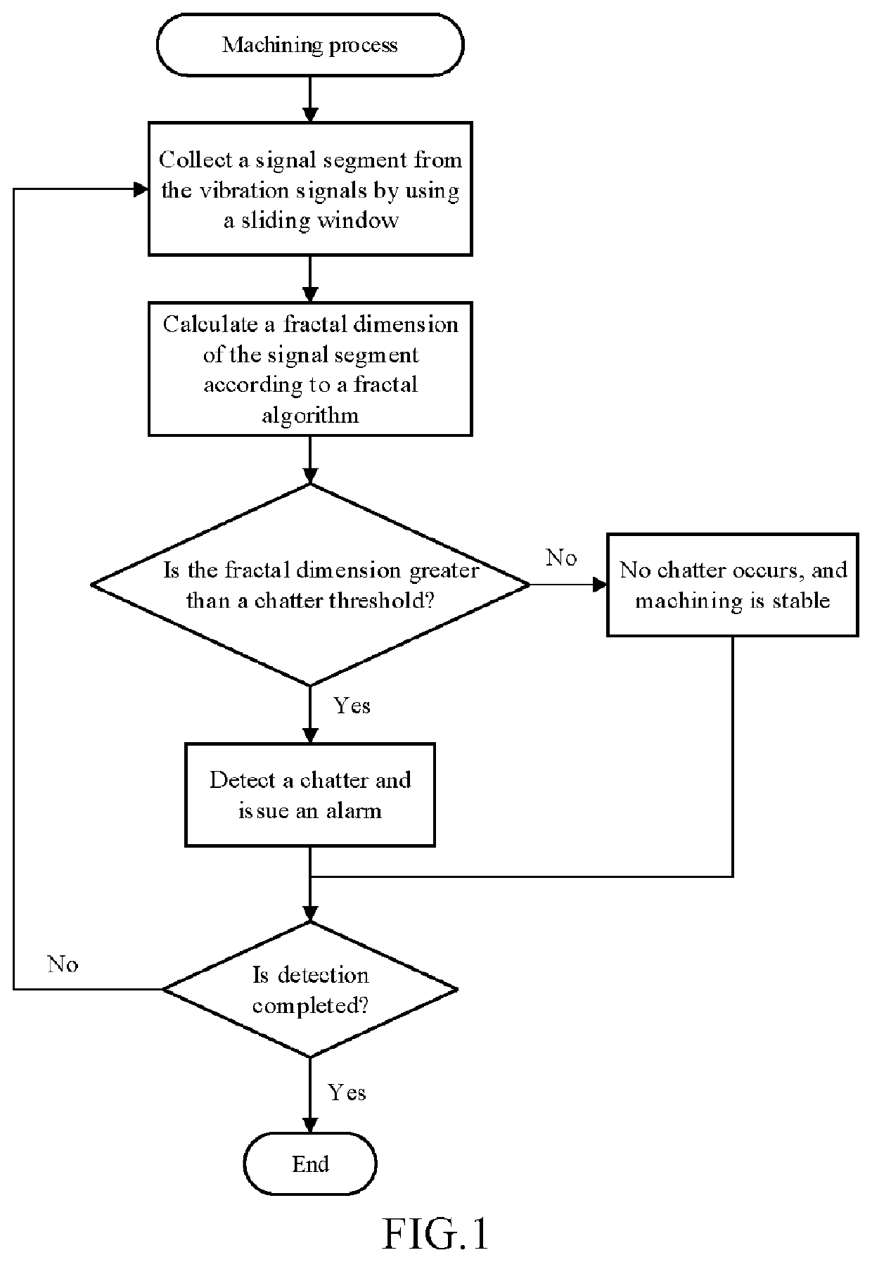
[0078]A method for monitoring chatter online in a machining process is provided. An implementation process is shown in FIG. 1, including the following steps.

[0079]Step 1: collecting original vibration signals in directions X, Y, and Z during milling by using a machine tool, a vibration sensor and a data collection card. Generally, when the machine tool chatters, the energy is mainly concentrated between 3000 Hz and 5000 Hz, so that a sampling frequency f is greater than 9600 Hz.

[0080]Step 2: in a sliding window model shown in FIG. 4, select N=800as the size of the sliding window according to the sampling frequency. If a step-length of the sliding window is one data point, the fractal dimension of the signal is calculated when a new data point is collected.

[0081]Step 3: data points given in the sliding window are pi=(xi, yi), i=1,2,3 . . . N, the signal waveform may be stretched or compressed in a horizontal direction and a vertical direction, the stretching and compression coefficie...

embodiment 3

[0086]A method for monitoring chatter online in a machining process is provided. Based on analysis for fractal signal of time series, an implementation process is shown in FIG. 1, including the following steps.

[0087]Step 1: collecting original vibration signals in directions X, Y, and Z during milling of a machine tool by using a vibration sensor and a data collection card. Generally, when the machine tool chatters, the energy is mainly concentrated between 3000 Hz and 6000Hz, so that a sampling frequency f is greater than 9600 Hz.

[0088]Step 2:in a sliding window model shown in FIG. 4, selecting N=800as the size of the sliding window according to the sampling frequency. If a step-length of the sliding window is one data point, the fractal dimension of the signal is calculated when a new data point is collected.

[0089]Step 3: setting the coordinate value of the data point as pi=(xi, yi), i=1,2,3 . . . N after the given data point in the sliding window is stretched and compressed. Then...


PUM


Abstract

A method for monitoring chatter in a machining process includes the following steps: collecting an original signal related to chatter in the machining process; for the original signal, obtaining a signal segment for calculation and analysis by updating data points in a sliding window with a set step-length, where the step-length refers to a number of data points updated every time in the sliding window, and is not greater than the size of the sliding window; calculating fractal dimensions of the signal segments in the sliding window by using a fractal algorithm; and comparing the calculated fractal dimension with an identification threshold to determine whether chatter occurs in the machining process. The measured signal does not need to be preprocessed by using the method, which can greatly improve calculation efficiency and can ensure accuracy of chatter identification.

Description

CROSS REFERENCE TO RELATED APPLICATIONS[0001]This application is a continuation application of PCT / CN2019 / 108453filed on 2019-Sep.-27, which claims priority to CN patent application NO. 201910832660.9 filed on 2019-Sep.-4. The contents of the above-mentioned application are all hereby incorporated by reference.BACKGROUND OF THE INVENTION1. Field of the Invention[0002]The present invention relates to an intelligent monitoring technology in the field of intelligent manufacturing, and in particular, to a method for monitoring chatter in machining process.2. Description of the Prior Art[0003]Machining methods include milling, turning, grinding, and the like. Chatter is spontaneous oscillation between a tool and a workpiece, which is a main factor affecting machining stability and quality of machined parts. Regenerative chatter is the most important chatter, whose mechanism is the phase difference between the wavy surfaces formed by the previous machining and the current one. The occurre...

Claims


Application Information

Patent Timeline
IPC IPC(8): B23Q17/12G01H1/00
CPCB23Q17/12G01H1/00G01H3/00G01H1/003
Inventor FENG, FENGXU, CHAOMEI, XUEYUFENG, PINGFAMA, YUAN
Owner SHENZHEN GRADUATE SCHOOL TSINGHUA UNIV
Learn More