Diffractive optical element, projection device, and measurement device

Active Publication Date: 2021-03-25
ASAHI GLASS CO LTD
View PDF0 Cites 0 Cited by
  • Summary
  • Abstract
  • Description
  • Claims
  • Application Information

AI Technical Summary

Benefits of technology

The invention is a special optical element that can capture and use light efficiently, making it possible to create devices that produce high-quality images. It can also reduce the unwanted generation of light that doesn't contribute to the image.

Problems solved by technology

Since the surfaces of the protrusions and the recesses are not exposed, this configuration can reduce a variation of diffraction efficiency caused by adhesion of substances.
In the case where the aspect ratio is increased, the ratio of the area of the side surfaces (of the protrusions) of the protrusion and recess portion capable of serving as interfaces for light traveling through the protrusion and recess portion to the area of all surfaces is increased, which may increase the influence of reflection at the side surfaces of protrusions and so on such that undesired 0th-order light may be generated.
Typically, irradiation of strong 0th-order light is considered to be undesirable from the viewpoint of safety of eyes.

Method used


Image

  • Diffractive optical element, projection device, and measurement device
  • Diffractive optical element, projection device, and measurement device
  • Diffractive optical element, projection device, and measurement device

Examples


example 1

[0088]This Example is a diffractive optical element 10 having a protrusion and recess portion 12 having a multilayer structure that constitutes a two-step protrusion and recess pattern and includes a base portion 123, like the example diffractive optical element 10 shown in FIG. 3C. However, in this Example, as shown in FIG. 8, an antireflection layer 14 is further provided on the surface of a substrate 11 opposite to its surface on which the protrusion and recess portion 12 is formed. The design wavelength is 850 nm and the recesses 122 are air (n=1).

[0089]In the diffractive optical element 10 of this Example, protrusion and recess patterns were designed so that the exit angle range θout (more specifically, diagonal viewing angle θd) of a diffraction light group that exits the protrusion and recess portion 12 became equal to 50°, 68°, 90°, 102°, 116°, 134°, and 164°, respectively. The Examples whose θd is 50°, 68°, 90°, 102°, 116°, 134°, and 164° are Examples 1A, 1B, 1C, 1D, 1E, 1F...

example 2

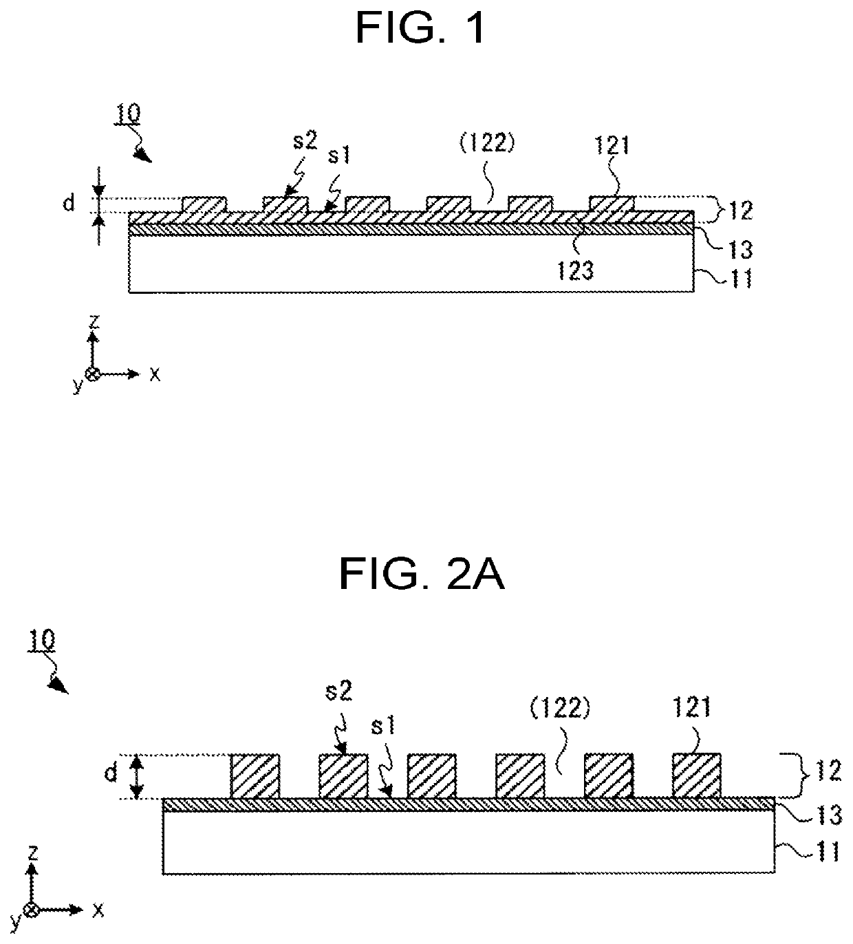
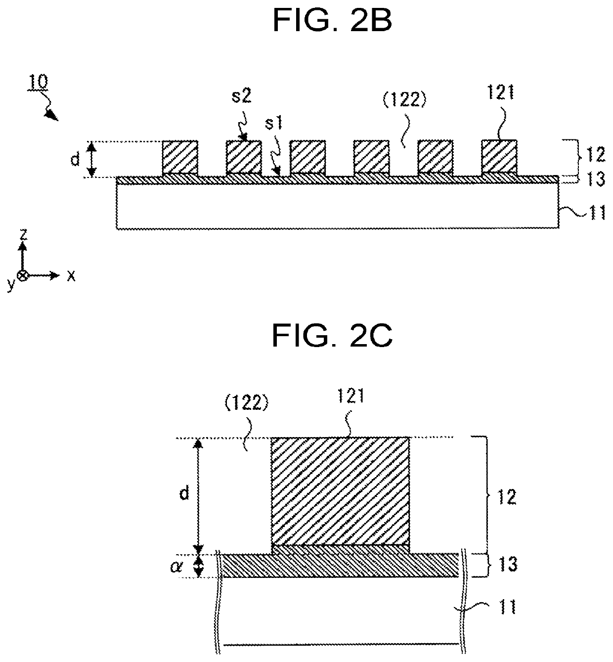
[0101]This Example is a diffractive optical element 10 having a protrusion and recess portion 12 having a multilayer structure that constitutes a two-step protrusion and recess pattern and does not include a base portion 123 like the example diffractive optical element 10 shown in FIG. 2A. However, also in this Example, an antireflection layer 14 is further provided on the surface of a substrate 11 opposite to its surface on which the protrusion and recess portion 12 is formed (see FIG. 8). More specifically, as shown in FIG. 2B and FIG. 2C, in this Example, portions of an internal antireflection layer 13 constitute a bottommost layer of the protrusions 121. However, these portions constituting parts of the protrusions 121 are 10 nm or less in thickness and hence are not regarded as parts of the protrusions 121 but as parts of the internal antireflection layer 13. The design wavelength is 850 nm and the recesses 122 are air (n=1).

[0102]Also in this Example, protrusion and recess pat...


PUM


Abstract

A diffractive optical element includes: a substrate; a protrusion and recess portion that is formed on one surface of the substrate and imposes predetermined diffraction on incident light; and an antireflection layer provided between the substrate and the protrusion and recess portion. An effective refractive index difference Δn in a wavelength range of the incident light between a first medium constituting a protrusion of the protrusion and recess portion and a second medium constituting a recess of the protrusion and recess portion is 0.70 or more. An exit angle range θout of diffraction light exiting from the protrusion and recess portion when the incident light enters the substrate from a normal direction of the substrate is 60° or more. Total efficiency of diffraction light exiting from the protrusion and recess portion in the exit angle range is 65% or more.

Description

TECHNICAL FIELD[0001]The present invention relates to a diffractive optical element that generates light spots having a predetermined pattern, and a projection device and a measurement device that are equipped with the diffractive optical element.BACKGROUND ART[0002]There is a device that measures a position, a shape, etc. of a measurement target object by applying predetermined light to the measurement target object and detecting light scattered by the measurement target object (refer to Patent document 1, for example). In the kind of measurement device, a diffractive optical element can be used for applying a particular light pattern to a measurement target.[0003]For example, there is a common diffractive optical element that is obtained by forming protrusions and recesses on a substrate surface. Diffractive optical elements having such a protrusion and recess structure diffract light by giving it a desired difference of optical path length utilizing a diffractive index difference...

Claims


Application Information

Patent Timeline
IPC IPC(8): G02B27/42G02B27/44G01B11/25
CPCG02B27/4222G01B11/2513G02B27/44G02B5/1814G02B1/11G03B21/14G02B1/115G02B5/18G03B21/00
Inventor MURAKAMI, RYOTANAKAYAMA, MOTOSHI
Owner ASAHI GLASS CO LTD
Why Eureka
Try Eureka